Apparatus and method for protecting an electric line

a technology of electric lines and accessories, applied in the direction of contact mechanisms, electric devices, manufacturing tools, etc., can solve the problems of reducing the service life of the fuse, wear and deterioration of the fuse, and destroying the electric lin

Active Publication Date: 2013-05-28
LISA DRAXLMAIER GMBH
View PDF28 Cites 9 Cited by
  • Summary
  • Abstract
  • Description
  • Claims
  • Application Information

AI Technical Summary

Benefits of technology

[0012]This apparatus offers the advantage that due to the combination of the electric fuse and the controllable switching element, preferably a power semiconductor, the switching element can absorb the pulse load, and so the electric fuse can be protected when there are pulse loads. Therefore, pulse loads acceptable by the line can occur in the apparatus without the fuse being triggered.

Problems solved by technology

However, temporary pulse loads, which are characterised by large current peaks, are particularly bad for the service life of a fuse since under certain circumstances the latter do not pose any problems for the electric line, but can however stress the fuse since the pulse loads come close to the actual triggering conditions, and so more frequently recurring pulse loads reduce the service life of the fuse.
If, for example, fuses fuse in a range of 40-50 A, repeated current peaks in the range over 30 A lead to wear and deterioration of the fuse.
However, then the line is not sufficiently protected in the range t>10 secs (uniformly distributed load) and overload currents (sluggish short circuit, overload) can lead to the destruction of the electric line.
Since the characteristics of the cut-out fuse and the line are not adapted, the designing of line sets inherently involves oversizing of the cross-sections of the electric lines, and so inefficient utilisation of the resources, e.g. copper.
An example of this type of poor adaptation is the protection of an engine with a nominal output of 140 W / 12 A. Since the engine draws a starting current which exceeds the nominal current six-fold, it cannot be protected with a 15 A fuse even though the electric line could carry this pulse load.

Method used


Image

  • Apparatus and method for protecting an electric line
  • Apparatus and method for protecting an electric line
  • Apparatus and method for protecting an electric line

Examples


Embodiment Construction

[0032]In the following preferred embodiments of the present invention are described in detail with reference to the accompanying drawings. Here the same or corresponding elements in the different drawings are respectively identified by the same or similar reference numbers.

[0033]The preferred embodiments of the invention, which are described in detail in the following, are described in detail with reference to an apparatus for protecting an electric line in a vehicle. It is noted, however, that the following description only includes examples, and should not be considered as restricting the invention.

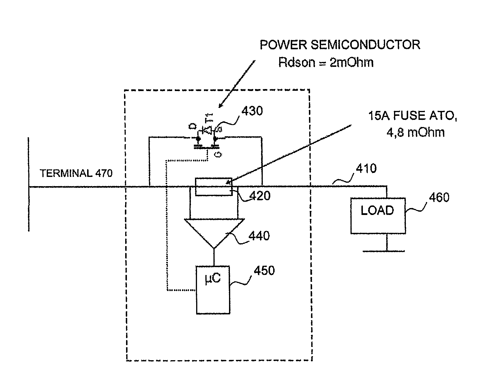
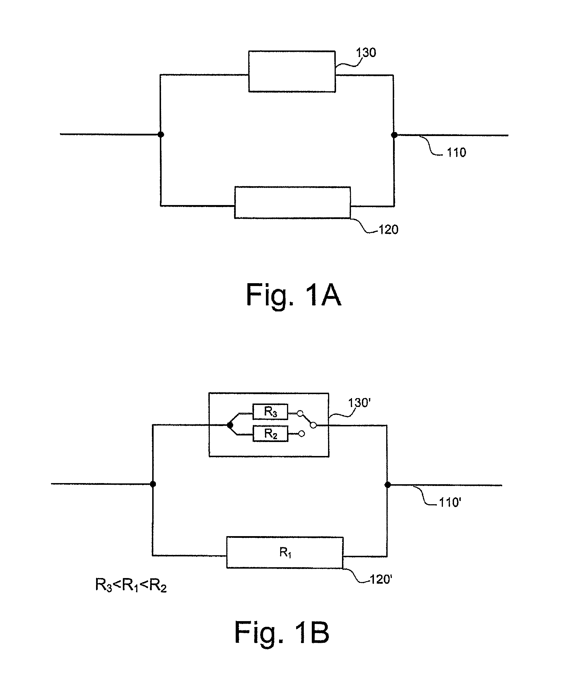
[0034]FIG. 1A shows diagrammatically elements of an apparatus for protecting an electric line 110 in a vehicle. The apparatus comprises an electric fuse 120 and a controllable switching element 130 which are formed as a parallel circuit, and the parallel circuit being connected in series to the electric line 110. Moreover, the electric fuse 120, as shown in FIG. 1A, is disposed in a fir...


PUM

PropertyMeasurementUnit
temperatureaaaaaaaaaa
electric resistance R1aaaaaaaaaa
currentaaaaaaaaaa

Abstract

The present invention relates to an apparatus and a method for protecting an electric line in a vehicle, it being possible to adapt the apparatus to the properties of the electric line to be protected. The apparatus for protecting an electric line comprises an electric fuse and a controllable switching element, the controllable switching element and the electric fuse being formed as a parallel circuit, and the parallel circuit being connectable in series to the electric line, the electric fuse being disposed in a first branch of the parallel circuit, which has a first resistance, and the controllable switching element being disposed in a second branch of the parallel circuit, and the controllable switching element being configured to accommodate at least two states, a first state with a second resistance higher than the first resistance, and a second state with a third resistance lower than the first resistance, and to switch into the second state when there is a pulse load condition.

Description

FIELD OF THE INVENTION[0001]The present invention relates to an apparatus and to a method for protecting an electric line in a vehicle, and in particular to an apparatus and to a method for protecting an electric fuse by means of a circuit element connected in parallel.PRIOR ART[0002]The protection of an electric line in a vehicle is generally implemented by means of a cut-out fuse which is typically designed for a uniformly distributed load of the electric line. However, temporary pulse loads, which are characterised by large current peaks, are particularly bad for the service life of a fuse since under certain circumstances the latter do not pose any problems for the electric line, but can however stress the fuse since the pulse loads come close to the actual triggering conditions, and so more frequently recurring pulse loads reduce the service life of the fuse. If, for example, fuses fuse in a range of 40-50 A, repeated current peaks in the range over 30 A lead to wear and deteri...

Claims


Application Information

Patent Timeline
Patent Type & Authority Patents(United States)
IPC IPC(8): H01H83/00H01H79/00
CPCH01H9/106H01H2085/0283
Inventor WORTBERG, MICHAEL
Owner LISA DRAXLMAIER GMBH
Why Eureka
Try Eureka