
Color adjustment method for color sequential liquid crystal display

a liquid crystal display and color adjustment technology, applied in the direction of instruments, static indicating devices, etc., can solve the problems of excessively high instantaneous power generation and deteriorated image quality, and achieve the effect of reducing the adverse effect of image quality and reducing instantaneous power

Inactive Publication Date: 2013-05-28
CHUNGHWA PICTURE TUBES LTD
View PDF9 Cites 0 Cited by
  • Summary
  • Abstract
  • Description
  • Claims
  • Application Information

AI Technical Summary

Benefits of technology

This patent is about a method to adjust the color on a LCD screen to reduce the impact of color breakup on image quality and to reduce the amount of power needed to display the screen. The method involves using a white light source to show a main field, which helps to improve image quality and reduces the need for a powerful light source.

Problems solved by technology

When a conventional color sequential LCD displays images, the color breakup phenomenon often occurs, thereby resulting in the deteriorated image quality.
However, since all of the LEDs emit light at the same time, an excessively high instantaneous power is generated when the white field is displayed.

Method used


Image

  • Color adjustment method for color sequential liquid crystal display
  • Color adjustment method for color sequential liquid crystal display
  • Color adjustment method for color sequential liquid crystal display

Examples


Embodiment Construction

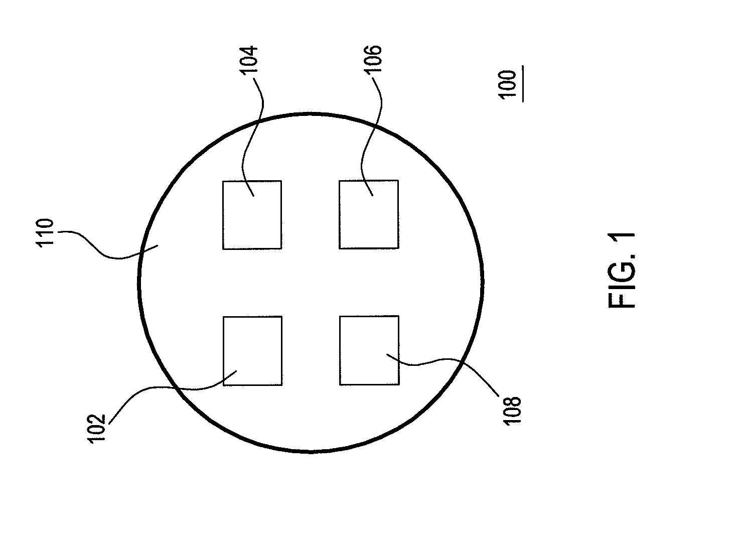
[0017]FIG. 1 shows a light source assembly applied in a color adjustment method for a color sequential LCD according to an embodiment of the present invention. Referring to FIG. 1, the color adjustment method according to this embodiment is applied in a color sequential LCD having at least one light source assembly 100, and the light source assembly 100 may be disposed in a backlight module of the color sequential LCD.

[0018]Based on the above, the light source assembly 100 includes at least one white light source 102, a plurality of monochromatic light sources 104, 106, and 108, and a circuit board 110. The white light source 102 and the monochromatic light sources 104, 106, and 108 are assembled on the circuit board 110, and all the white light source 102 and the monochromatic light sources 104, 106, and 108 may be LEDs.

[0019]In detail, the white light source 102 may be a white LED, and the monochromatic light sources 104, 106, and 108 may be a red LED, a green LED, and a blue LED ...


PUM


Abstract

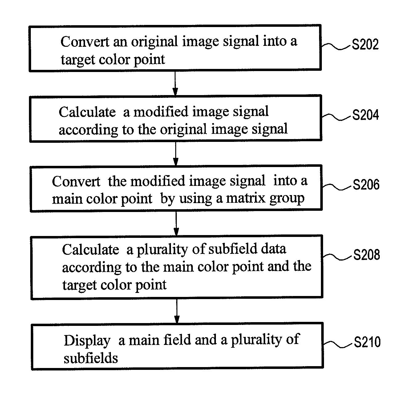
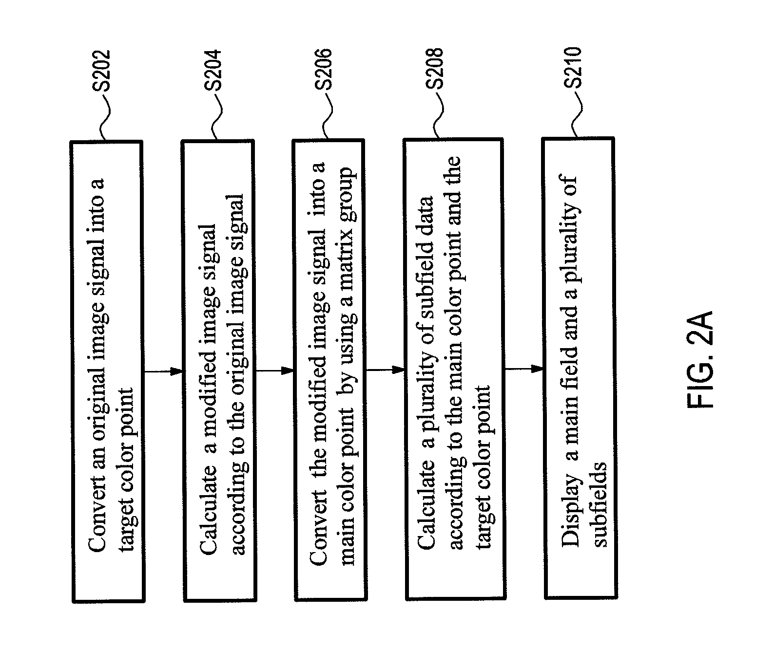
A color adjustment method for a color sequential liquid crystal display (LCD) having at least one white light source is provided. In the color adjustment method, firstly, an original image signal is converted into a target color point located in a chromaticity diagram in a color space. Then, a modified image signal having white data is calculated according to the original image signal. Afterwards, the modified image signal is converted into a main color point located in the chromaticity diagram by using a matrix group. Then, a plurality of subfield data are calculated according to the main color point and the target color point. The subfield data are used for enabling the main color point to fall on the target color point.

Description

CROSS-REFERENCE TO RELATED APPLICATION[0001]This application claims the benefit of Taiwan Patent Application No. 099103317, filed on Feb. 4, 2010, which is hereby incorporated by reference for all purposes as if fully set forth herein.BACKGROUND OF THE INVENTION[0002]1. Field of the Invention[0003]The present invention relates to an image adjustment method for a display, and more particularly to a color adjustment method for a color sequential liquid crystal display (LCD).[0004]2. Related Art[0005]When a conventional color sequential LCD displays images, the color breakup phenomenon often occurs, thereby resulting in the deteriorated image quality. In detail, when the conventional color sequential LCD displays a dynamic image with a moving object, a viewer stares at the object unconsciously, and tracks the movement of the object.[0006]At this time, three primary color fields forming an image of the object, that is, a red field, a green field, and a blue field, are not projected onto...

Claims


Application Information

Patent Timeline
Patent Type & Authority Patents(United States)
IPC IPC(8): G09G3/36
CPCG09G3/36G09G3/3413G09G2310/0235G09G2340/06G09G2320/0242G09G2320/0666
Inventor HUANG, YI-PAISHIEH, HAN-PINGCHEN, YI-LINGLIN, FANG-CHENGCHEN, CHUN-HOTAI, WEN-CHIHCHIOU, SHIAN-JUN
Owner CHUNGHWA PICTURE TUBES LTD
Learn More