Poppet valve with sloped purge holes and method for reducing a pressure force therein

a technology of purge hole and poppet valve, which is applied in the direction of valve operating means/release devices, machines/engines, and positive displacement liquid engines, etc., can solve the problems of increasing valve weight and cost, reducing the maintenance time between failures, and reducing compressor efficiency, so as to reduce static pressure, reduce the required differential pressure, and reduce the effect of gas pressure for

Active Publication Date: 2013-06-04
NUOVO PIGNONE TECH SRL
View PDF9 Cites 0 Cited by
  • Summary
  • Abstract
  • Description
  • Claims
  • Application Information

AI Technical Summary

Benefits of technology

[0009]By accelerating the gas flow in the rear portion of a poppet valve, a reduced static pressure inside a purged internal chamber of the valve is achieved, thereby reducing a gas pressure force acting on a poppet shutter to cause the valve to close, reducing the required differential pressure along the valve to open it, and stabilizing the dynamic opening of the valve.
[0012]Methods for reducing a closing pressure force acting on a poppet shutter of a poppet valve are also with the scope of the subject matter disclosed herein. These methods include steps of accelerating the flow in a flow passage of the valve so as to reduce the static pressure in a region of the flow passage between an inlet and an outlet of the valve, a portion of this flow passage being formed between a poppet guide and a valve body; and placing an inner chamber of the poppet guide in now communication with the region of reduced static pressure of the flow passage so as to reduce a fluid pressure force acting against an inner surface of the poppet toward an inner surface of the valve body.

Problems solved by technology

In this case, a reduced flow area may cause increased pressure losses and higher gas temperatures, leading to losses in compressor efficiency.
Furthermore, an unstable motion of the shutter may also lead to a reduction in maintenance time between failures due mainly to the increase in the number of impacts between mobile and stationary parts.
Yet another example relates to the requirement to maintain impact velocities between mobile and stationary parts within allowable limits in order to prevent or minimize impact surface wear and the need to unnecessarily increasing the impact strength of valve components, thus increasing valve weight and cost.
Finally, another example of a design constraint is the requirement for low sensitivity to a sticking phenomenon caused by, among other factors, the presence of lubricating oil and other contaminants in the gas causing sticking in various surfaces in contact with one another, resulting in impact velocity increases and valve closure delays.
Different factors, such as high gas temperatures, early wear, the presence of polymers, or loud noise, may be an indication of poor valve performance that may result in a reduction in the lifetime of the valve.

Method used


Image

  • Poppet valve with sloped purge holes and method for reducing a pressure force therein
  • Poppet valve with sloped purge holes and method for reducing a pressure force therein
  • Poppet valve with sloped purge holes and method for reducing a pressure force therein

Examples


Embodiment Construction

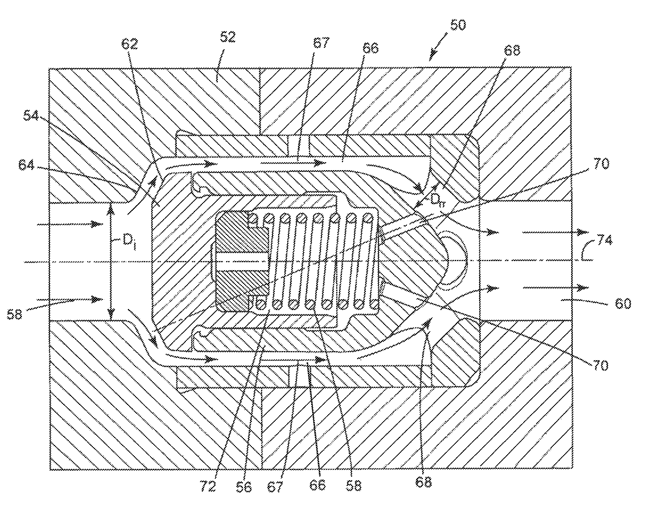
[0020]Embodiments of the subject matter disclosed herein relate generally to compressors and more particularly to poppet valves of hyper compressors with improved purge holes. By accelerating the gas flow in the rear portion of the valve, a reduced static pressure inside a purged inner chamber of a poppet guide develops, thereby reducing a gas pressure force acting on the internal chamber to cause the valve to close, reducing the required differential pressure along the valve to open it, and stabilizing the dynamic process associated with the opening of the valve. Referring now to the drawings, wherein like reference numerals designate identical or corresponding parts throughout the several views, several embodiments of poppet valves disclosed herein will be described.

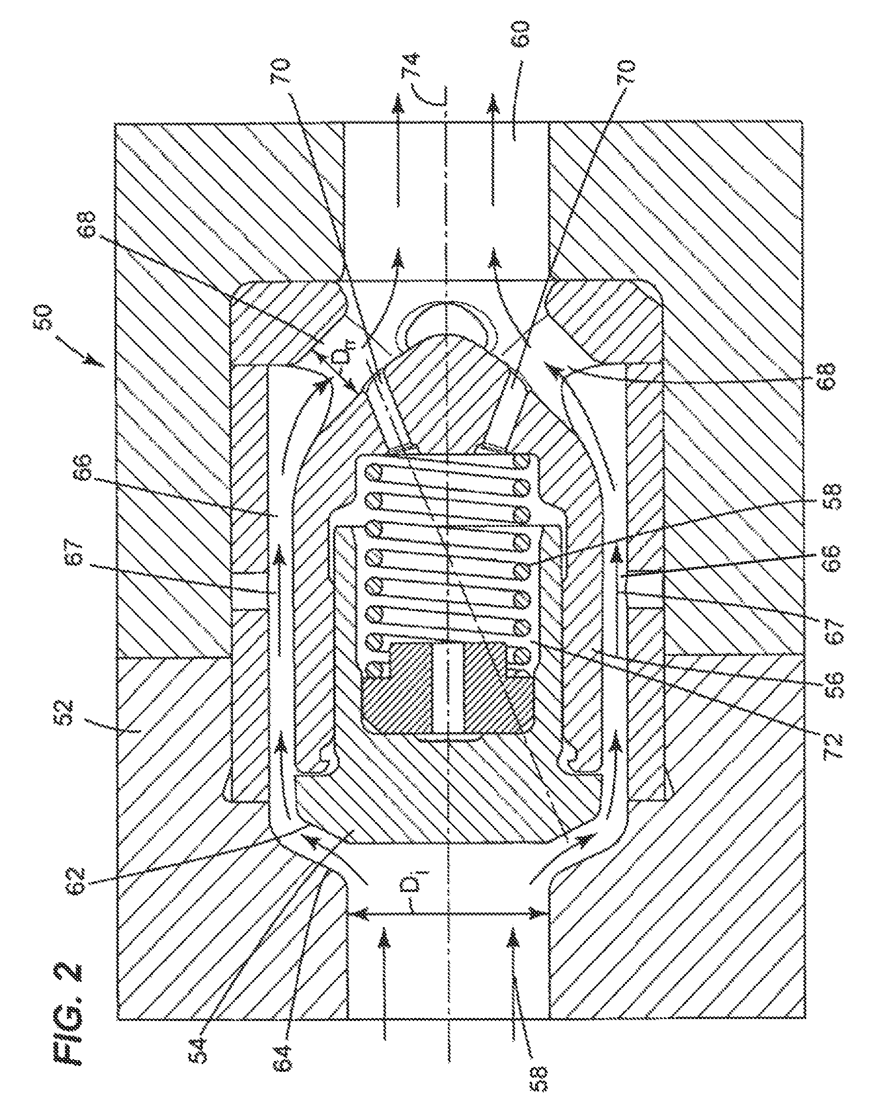
[0021]FIG. 2 illustrates a poppet valve 50 in accordance with an exemplary embodiment of the subject matter disclosed. As understood by those of ordinary skill in the applicable arts, the poppet valve 50 may either be ...


PUM


Abstract

A poppet valve is disclosed that includes a valve body, a poppet guide disposed inside the valve body so as to form a flow passage from an inlet to an outlet of the valve, a poppet shutter disposed inside the poppet guide, and a biasing member to bias the poppet shutter away from the poppet guide toward an inside surface of the flow inlet so as to block the flow passage. The poppet valve further includes at least one discharge hole placing an inner chamber of the poppet guide in flow communication with a region of low static pressure of the flow passage. A method for reducing a closing pressure force acting on a poppet shutter of a poppet valve is also disclosed.

Description

BACKGROUND OF THE INVENTION[0001]1. Field of the Invention[0002]The embodiments disclosed relate generally to compressors and more particularly to poppet valves of hyper compressors with improved purge holes.[0003]2. Description of the Related Art[0004]Hyper compressors, those capable of producing gas pressure levels up to or above 3,000 bars, are widely used in industrial application, including, but not limited to, the production of low density polyethylene, or LDPE. The efficient performance of these compressors is controlled at least in part by suction and discharge automatic poppet valves. FIG. 1 illustrates a conventional poppet valve 10 in an opened position. As shown, the conventional poppet valve 10 includes a valve body 11 that contains therein a poppet, or poppet shutter, 12 configured to open and close the gas flow path in and out of a hyper compressor, a spring 14 configured to keep the poppet 12 in a closed position, and a poppet guide 16 that contains the poppet 12 and...

Claims


Application Information

Patent Timeline
Patent Type & Authority Patents(United States)
IPC IPC(8): F16K17/34
CPCF04B39/1013F16K15/026F16K17/065Y10T137/7839Y10T137/7754Y10T137/7852
Inventor FRANCINI, STEFANOCAMPO, NICOLABIANCHINI, MICHELE
Owner NUOVO PIGNONE TECH SRL
Why Eureka
Try Eureka