

Poppet valve with diverging-converging flow passage and method to reduce total pressure loss
a technology of diverging flow passage and poppet valve, which is applied in the field of compressors, can solve the problems of increasing valve weight and cost, reducing maintenance time between failures, and reducing compressor efficiency, so as to reduce static pressure, improve performance, and reduce backpressure. the effect of for
- Summary
- Abstract
- Description
- Claims
- Application Information
AI Technical Summary
Benefits of technology
Problems solved by technology
Method used
Image

Examples
Embodiment Construction
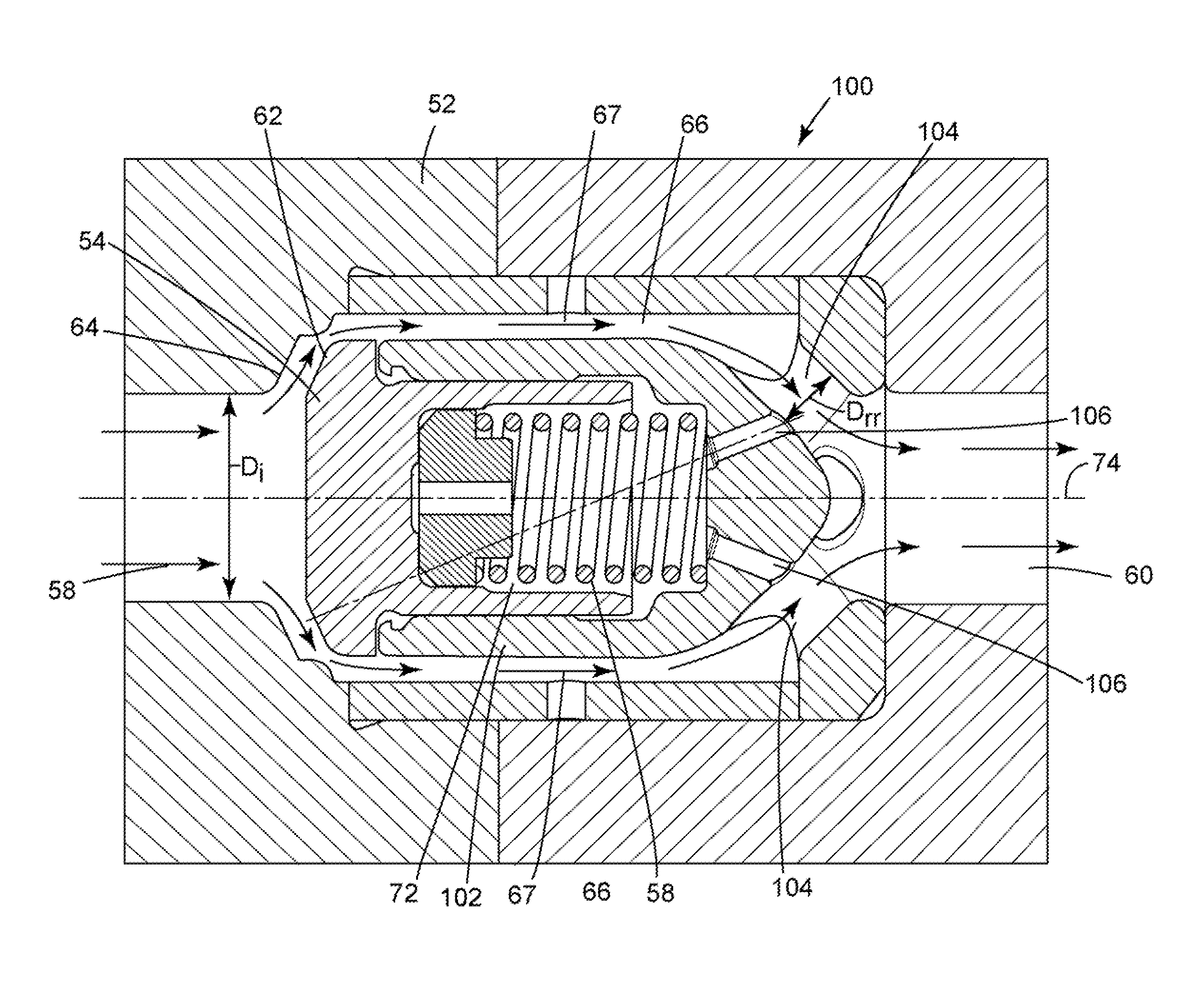
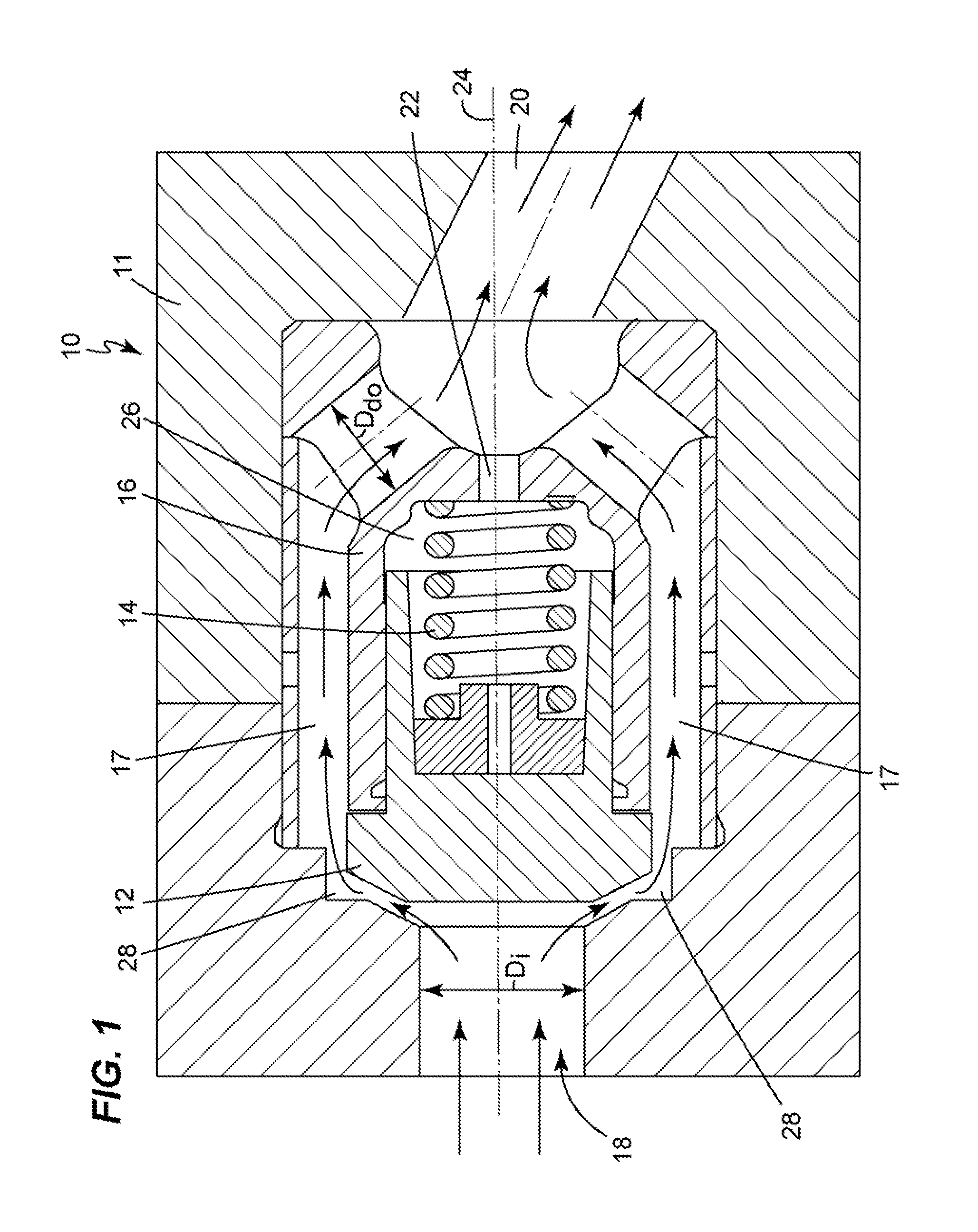
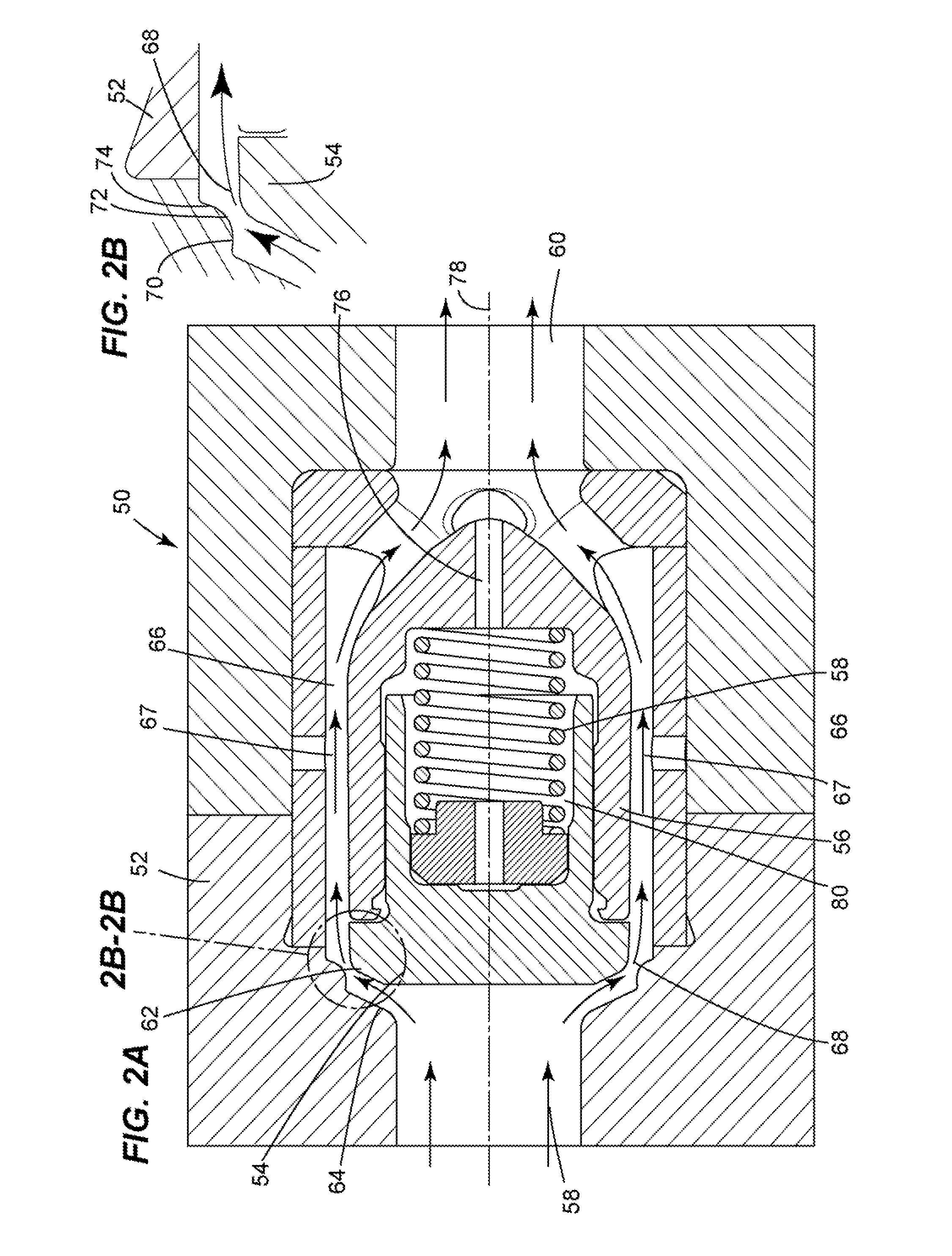
[0023]Embodiments of the subject matter disclosed herein relate generally to compressors and more particularly to poppet valves of hyper compressors that include a converging-diverging flow passage to reduce total pressure loss during the opening process. One of the controlling variables during the opening process of a poppet valve is the total pressure loss along the flow path. By forming a converging-diverging flow passage between the poppet shutter and an internal surface of the valve body against which the poppet shutter seats, the localized pressure loss in the region of the converging-diverging flow passage is controlled so as to reduce as the valve opens, thereby improving performance during the entire valve-opening process. In addition, in order to reduce the force generated by the backpressure acting on the poppet chamber, a reduced static pressure inside the valve chamber may be generated by one of two structural features of the subject matter disclosed. The first feature ...
PUM
 Abstract
Description
Claims
Application Information