Method and system for an energy assisted magnetic recording head having a suspension-mounted laser

a technology of suspension-mounted laser and magnetic recording head, which is applied in the field of method and system of suspension-mounted laser for energy assisted magnetic recording head, can solve the problems of time-consuming, prone to errors, and the throughput and yield of conventional eamr disk drive manufacturing, and the performance of conventional eamr disk drive may be adversely affected, and the effect of affecting the performance of the conventional eamr disk driv

Active Publication Date: 2013-06-04
WESTERN DIGITAL TECH INC
View PDF36 Cites 151 Cited by
  • Summary
  • Abstract
  • Description
  • Claims
  • Application Information

AI Technical Summary

Problems solved by technology

More specifically, aligning the laser 30 and optical component 32 to the desired position with respect to the conventional transducer 28 is time consuming and prone to error.
The throughput and yield of a manufacturing for fabricating the conventional EAMR disk drive 10 may thus be adversely affected.
Misalignment of the laser 30 with respect to the EAMR transducer 28 may also negatively impact performance of the conventional EAMR disk drive 10.

Method used


Image

  • Method and system for an energy assisted magnetic recording head having a suspension-mounted laser
  • Method and system for an energy assisted magnetic recording head having a suspension-mounted laser
  • Method and system for an energy assisted magnetic recording head having a suspension-mounted laser

Examples


Embodiment Construction

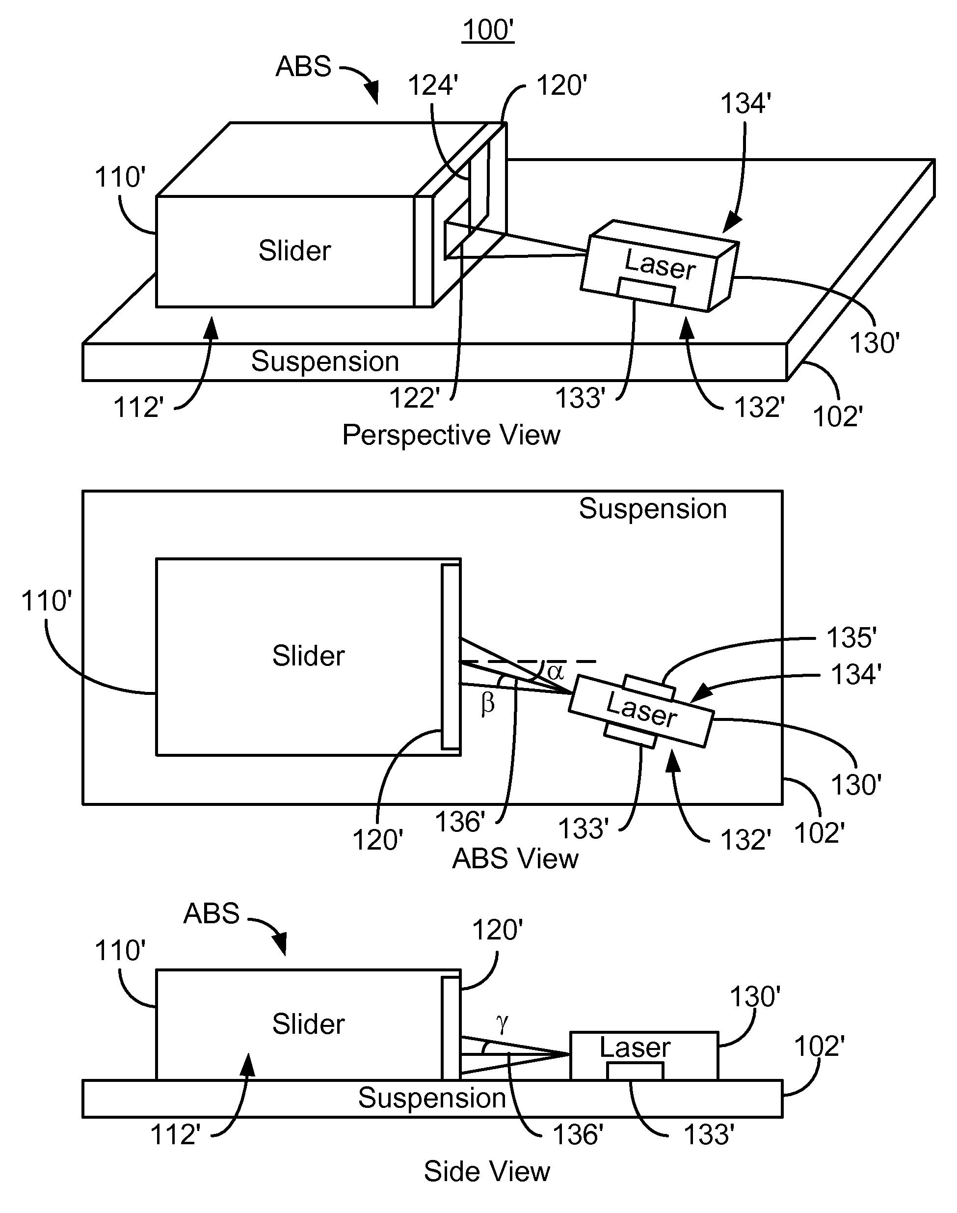
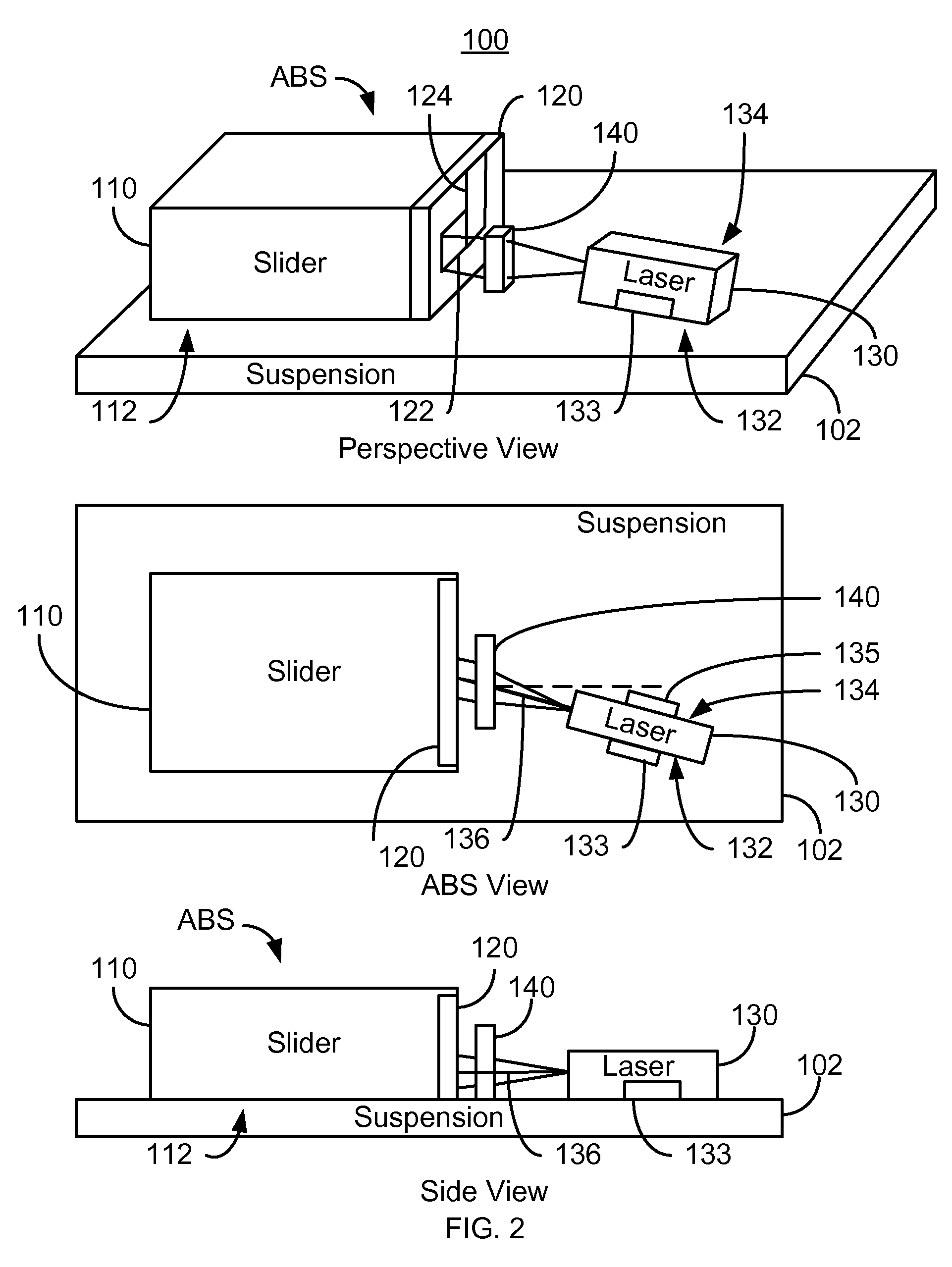
[0015]FIG. 2 is a diagram depicting a portion of an EAMR disk drive 100. For clarity, FIG. 2 is not to scale. For simplicity not all portions of the EAMR disk drive 100 are shown. In addition, although the disk drive 100 is depicted in the context of particular components other and / or different components may be used. Further, the arrangement of components may vary in different embodiments. In addition, although the EAMR disk drive 100 is described in the context of single components, multiple components may be used. For example, although described as including a single laser and a single EAMR transducer, the EAMR disk drive 100 may include multiple lasers and / or multiple EAMR transducers. The EAMR disk drive 100 includes suspension 102, a slider 110, an EAMR transducer 120, laser 130, and optional optics 140. The EAMR transducer 120 is optically coupled with the laser 130.

[0016]The EAMR transducer 120 is coupled with the slider 110. Although described as coupled to the slider 110, ...


PUM

PropertyMeasurementUnit
angleaaaaaaaaaa
angleaaaaaaaaaa
angleaaaaaaaaaa

Abstract

An energy assisted magnetic recording (EAMR) disk drive comprises a suspension and a slider having a back side, a laser-facing surface, and an air-bearing surface (ABS) opposite the back side. The slider is mounted to the suspension on the back side. The disk drive further comprises an EAMR transducer coupled with the slider, a portion of the EAMR transducer residing in proximity to the ABS and on the laser-facing surface of the slider. The disk drive further comprises a laser coupled with the suspension and having a light emitting surface facing the laser-facing surface of the slider. The laser has an optic axis substantially parallel to the suspension. The laser provides energy substantially along the optic axis and is optically coupled with the EAMR transducer via free space. The EAMR transducer receives the energy from the laser and writes to the media using the energy.

Description

BACKGROUND[0001]FIG. 1 depicts a side view of portion of a conventional energy assisted magnetic recording (EAMR) disk drive 10. The conventional EAMR disk drive 10 includes a recording media 12, a conventional slider 20, and a conventional laser diode 30 that are typically attached to a suspension (not shown). The conventional slider 20 has a leading edge 22, a trailing edge 26, and a back side 24. Other components that may be part of the conventional EAMR disk drive 10 are not shown. The conventional slider 20 is typically attached to the suspension at its back side 24. A conventional EAMR transducer 28 is coupled with the slider 20.[0002]The laser diode 30 is coupled in proximity to the EAMR transducer 28 on the trailing edge 26 of the slider 20. Light from the conventional laser diode 30 is provided substantially along the optic axis of the conventional laser diode 30 to the trailing edge 26 of the slider 20. Thus, the laser diode 30 may be oriented at a nonzero angle from the b...

Claims


Application Information

Patent Timeline
Patent Type & Authority Patents(United States)
IPC IPC(8): G11B11/00
CPCG11B5/314G11B5/4866G11B5/6088G11B2005/0021
Inventor HU, YUFENGLI, RUOLINTRAN, UTLI, JINSHAN
Owner WESTERN DIGITAL TECH INC
Why Eureka
Try Eureka