
Single axis solar tracking system

a solar tracking system and single axis technology, applied in the safety of solar heat collectors, light and heating equipment, photovoltaic supports, etc., can solve the problems of ineffective transmission of moment forces, ineffective transmission of rotary motion applied by the system on the worm gear, and inability to effectively transmit solar array worm gear to the drive shaft linkage, etc., to achieve the effect of maximizing economic performan

Active Publication Date: 2013-06-11
ARRAY TECH
View PDF73 Cites 121 Cited by
  • Summary
  • Abstract
  • Description
  • Claims
  • Application Information

AI Technical Summary

Benefits of technology

[0024]An object of the presently claimed invention is to mechanically link multiple solar trackers in a large array configuration so that they may operate in unison, driven by a single motor and tracker controller, whereby the mechanical linkage system is favorably designed such that it must only be capable of withstanding the relatively low forces required to effect movement of the trackers without the requirement to resist the larger forces induced from the wind that is applied to the array of trackers. Another object of the presently claimed invention is to contain these external wind forces within the supports of each individual solar tracker so that no extra foundations or attachments are necessary. A further object is to apply the drive principals to various solar single-axis tracking geometries to maximize the economic performance for each solar tracking application.
[0025]The mechanical drive system of the presently claimed invention advantageously links multiple single axis trackers together, moving many trackers through a simple and structurally minimal linkage to decrease cost and increase long term reliability. The configuration of the mechanical linkage and gear drive assemblies allows the motor to move the linked trackers, yet eliminates the transmission of the external wind forces to the drive linkage. By exploiting the “one way” drive properties of the presently claimed invention, the mechanical linkage need only transmit the relatively small forces necessary to move the tracker, and is not subject to the relatively high forces induced by the wind on the tracker. An added benefit of the system is that a relatively small motor can move a large area of solar modules. The drive system of the presently claimed invention is applicable to all solar tracking geometries. The mechanical drive configuration results in a very reliable, flexible, low cost tracking method that is easy to install and maintain. The various embodiments of the presently claimed invention apply the drive system to the appropriate tracking geometry in order to maximize the economic benefit of the tracking system.
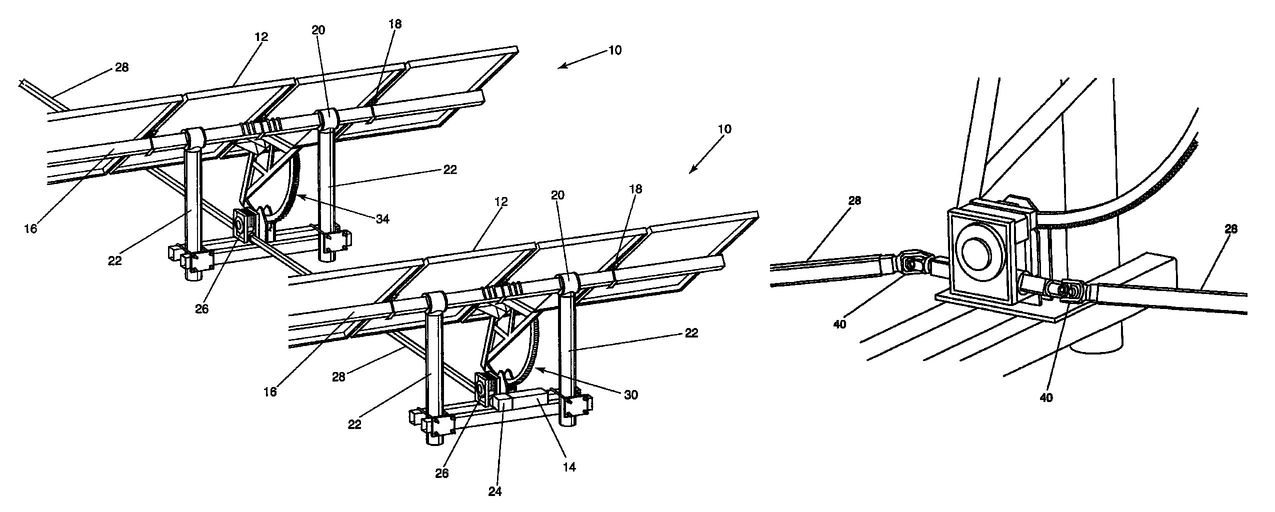
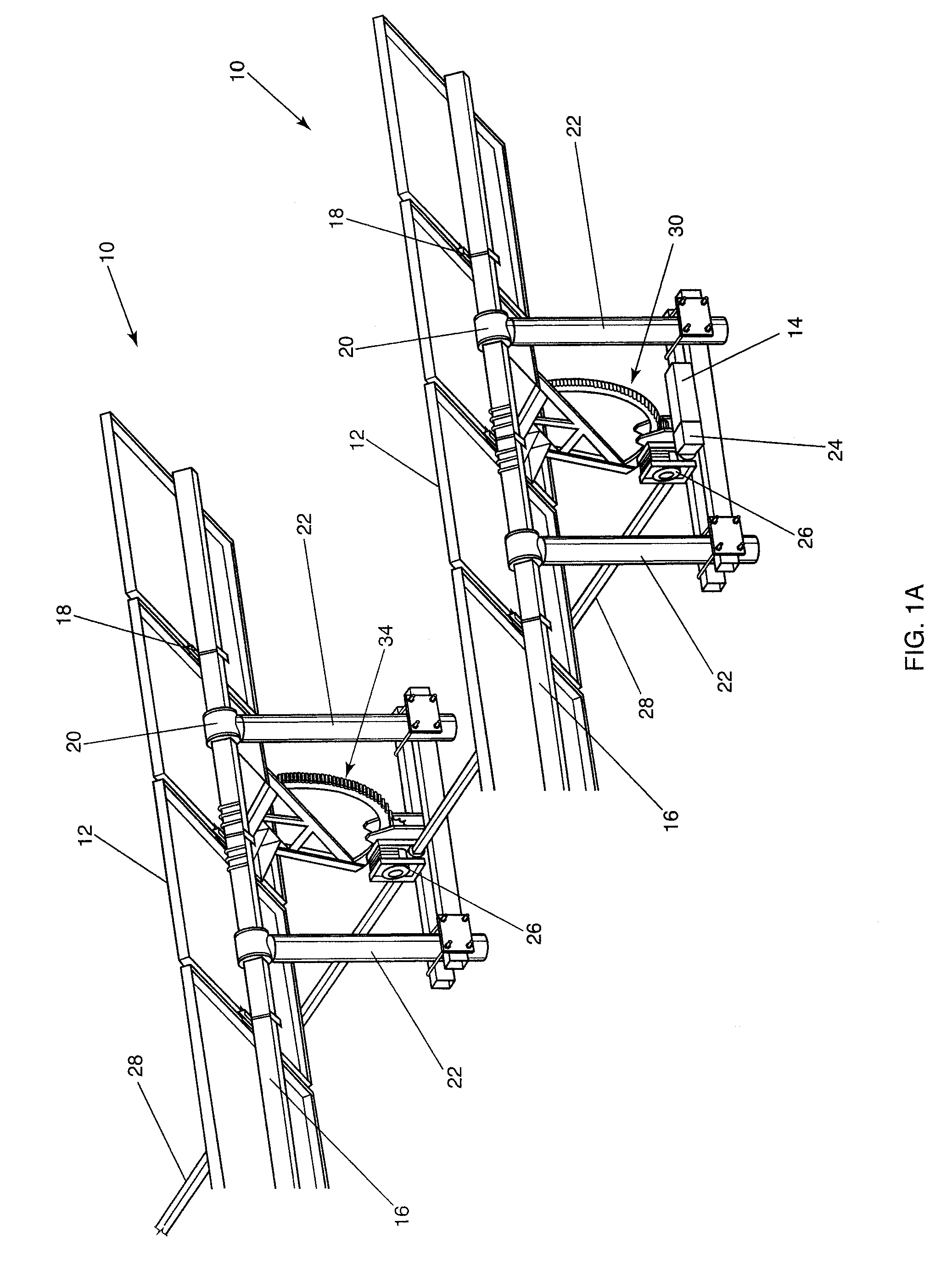
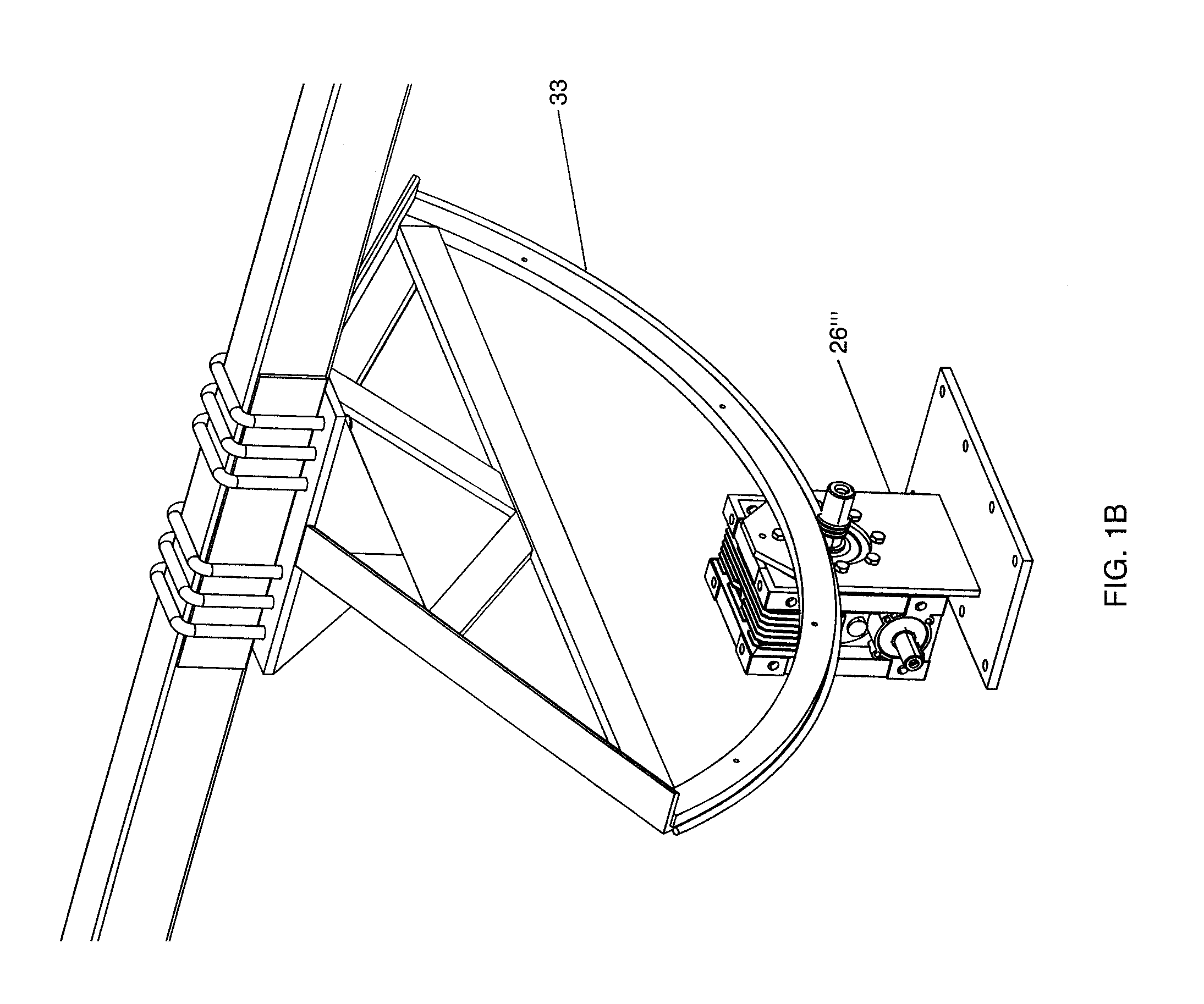
[0026]One aspect of the disclosed embodiments is to drive mechanically linked multiple rows of a horizontal S / A solar tracking collector assembly. Rows of solar modules are formed by affixing the solar modules to a generally horizontally positioned torsion tube having its long axis oriented in a north / south (N / S) direction. Each row includes one or more supports to the north and south of center and as well as the possible use of a center support. A bearing is affixed at each torsion tube support such that rotary motion of the torsion tube may be affected through a single stage worm-gear drive assembly or through a worm-drive gear assembly which includes a second stage gear that is affixed to the torsion tube and one or more supports. A driven, rotating drive shaft is affixed to both sides of the worm-drive assembly. The drive shaft may be positioned at right angles to the torsion tube and attached to each worm-gear drive to enable rotary motion of the torsion tube by applying rotary motion to the driven drive shaft. Back driving of the gearbox from wind forces applied to the system is virtually eliminated through the properties inherent in the design of the primary worm-drive gear assembly located at each tracker. The worm-drive gear assembly can be efficiently driven by the input of rotary motion from the drive shaft to the worm, but is very inefficient at transmitting rotary motion applied by the system on the worm-gear. Therefore, moment forces, induced by the wind, applied to the solar array cannot be effectively transmitted to the drive shaft linkage. The result is that the drive shaft does not need to resist the forces of the wind on the array and only transmits the driving force from the motor through a highly geared transmission system. This enables the drive shaft to be minimally constructed and allows for flexibility in its design and layout within the solar tracker array field.

Problems solved by technology

The worm-drive gear assembly can be efficiently driven by the input of rotary motion from the drive shaft to the worm, but is very inefficient at transmitting rotary motion applied by the system on the worm-gear.
Therefore, moment forces, induced by the wind, applied to the solar array cannot be effectively transmitted to the drive shaft linkage.

Method used


Image

  • Single axis solar tracking system
  • Single axis solar tracking system
  • Single axis solar tracking system

Examples


Embodiment Construction

Best Modes for Carrying Out the Invention

[0047]The presently claimed invention has four embodiments, a horizontal axis, a fixed tilt azimuth, tilt and roll, and a carousel tracker with the commonality of being linked together mechanically and operated by a rotary driven worm-drive system. All the tracker geometries incorporate a worm-gear primary drive, either attached to the tracker frame directly or through a secondary stage such as a spur gear rack, D-ring chain drive, or cable system mounted to one or two column support for the tracker. The disclosed embodiment allows many tracker rows to be driven by one drive motor through the mechanical drive shaft linkage, which does not need to resist the external forces applied to the array.

Horizontal Single Axis

[0048]The mechanically linked horizontal, single axis embodiment of the presently claimed invention is a tracking assembly 10 for pointing one or more solar panels or PV modules 12 towards the sun, as shown in FIG. 1A. Drive mechan...


PUM


Abstract

A solar tracking system with a torque tube supporting solar panels. Columns support the system and have bearings for rotation of the torque tube. A drive is coupled to the torque tube and is driven by a gearbox, such as a worm gear assembly, for rotating the array of solar panels to follow the sun's diurnal motion. The array can rotate in an opposite direction, or backtrack, to prevent shadowing from one module row to another. Multiple gearboxes can be mechanically linked by drive shafts and driven by a single motor. The drive shafts may incorporate universal joints for uneven terrain or staggered configurations. Harmonic dampers can be affixed to the solar panels to decouple wind forces which allows the use of larger solar panels.

Description

RELATED APPLICATIONS[0001]This application claims the benefit of provisional U.S. Application Ser. No. 60 / 934,557, entitled “SINGLE AXIS SOLAR TRACKING SYSTEM” filed Jun. 15, 2007, which is incorporated herein by reference in its entirety.BACKGROUND OF THE INVENTION[0002]1. Field of the Invention (Technical Field)[0003]The presently claimed invention relates to solar energy production and more particularly to a method and apparatus for constructing mechanically linked, single axis solar tracking systems of various tracking geometries to follow the diurnal motion of the sun.[0004]2. Background Art[0005]Solar tracking systems utilized in renewable energy production are devices that track the motion of the sun relative to the earth to maximize the production of solar energy. Solar trackers move to keep solar modules perpendicular to the sun in either one or two axes. The presently claimed invention applies to photovoltaic modules (PV) for generating electrical powers but may be applied...

Claims


Application Information

Patent Timeline
Patent Type & Authority Patents(United States)
IPC IPC(8): F24J2/38F24S50/20
CPCF24J2/5406F24J2/541H02S20/00F24J2/4638F24J2002/0084F24J2002/5468F24J2002/5496Y02E10/47Y02E10/50F24J2002/5462H02S20/32H02S20/10F24S2030/19F24S40/85F24S30/422F24S2030/134F24S2020/16F24S30/425F24S2030/136
Inventor CORIO, RONALD P.
Owner ARRAY TECH
Learn More