Stacked multi-port connector

a multi-port connector and connector technology, applied in the direction of coupling device connection, two-part coupling device, electrical apparatus, etc., can solve the problems of increasing the transmission frequency relatively, increasing the risk of noise interference, and affecting the stability of network signal transmission, so as to achieve a high level of signal transmission stability and effective protection of signal transmission

Inactive Publication Date: 2013-06-11
U D ELECTRONIC CORP
View PDF9 Cites 6 Cited by
  • Summary
  • Abstract
  • Description
  • Claims
  • Application Information

AI Technical Summary

Benefits of technology

[0010]The present invention has been accomplished under the circumstances in view. It is therefore the main object of the present invention to provide a stacked multi-port connector, which effectively protects signal transmission from electromagnetic interference, assuring a high level of signal transmission stability.

Problems solved by technology

However, increasing the transmission frequency relatively increases the risk of noise interference.
This problem will be more serious in stacked multi-port connector.
During operation of the stacked multi-port connector, the signal of the light-emitting devices C may interfere with the network signal being transmitted through the mating terminals A21, affecting network signal transmission stability.
This noise interference problem will become serious when the number of the mating slots A1 and the number of the pins C1 of the light-emitting devices C are increased.

Method used


Image

  • Stacked multi-port connector
  • Stacked multi-port connector
  • Stacked multi-port connector

Examples


Embodiment Construction

[0023]Reference will be made in detail to the preferred embodiment of the invention, an example of which is illustrated in the accompanying drawings. Wherever possible, like reference numbers are used in the drawings and the description to refer to like parts.

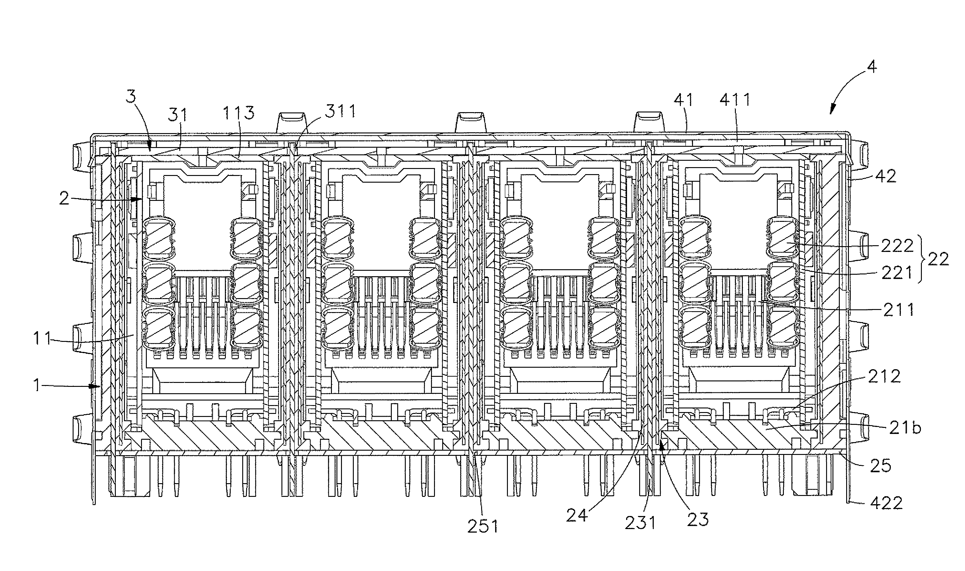
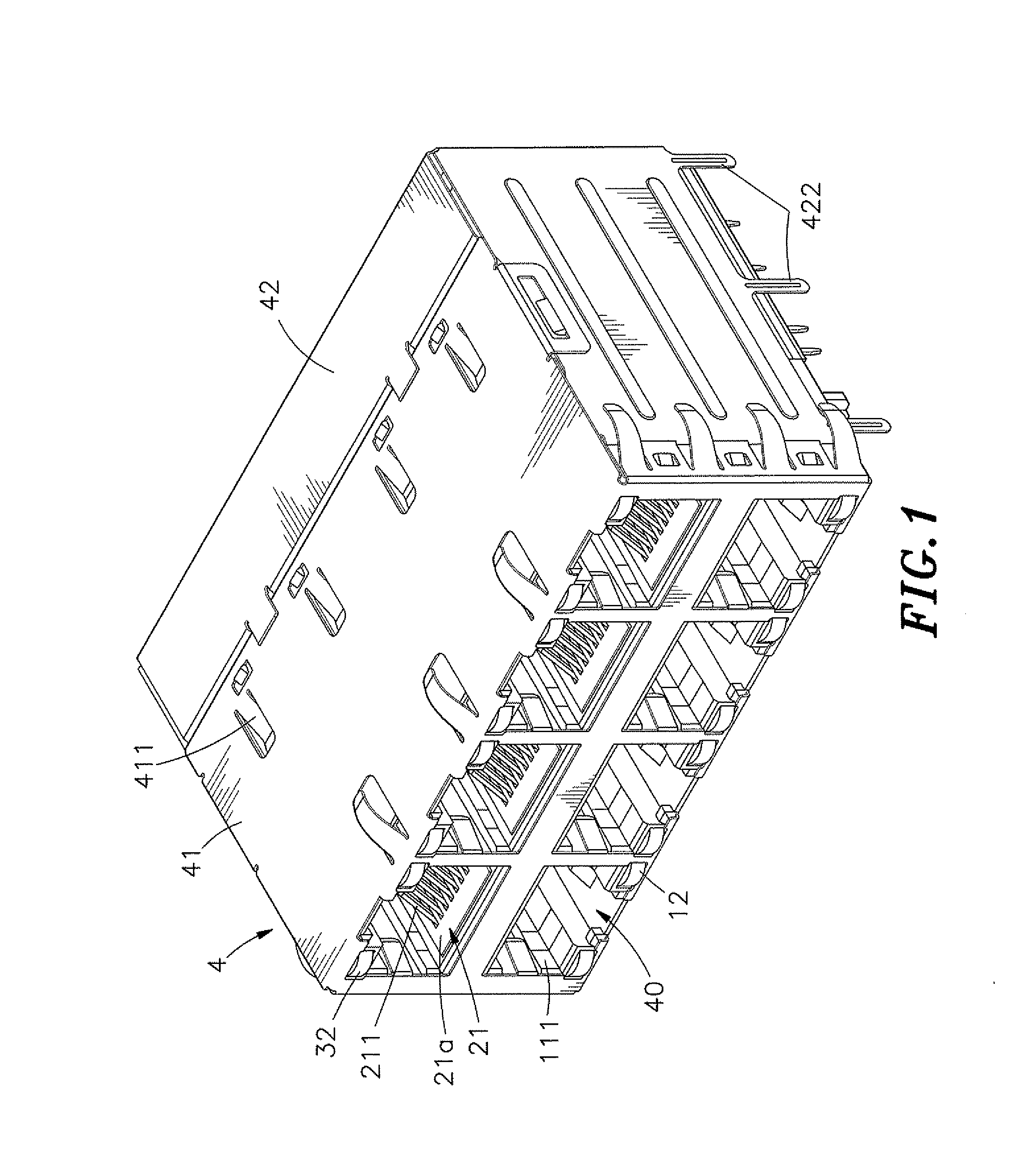
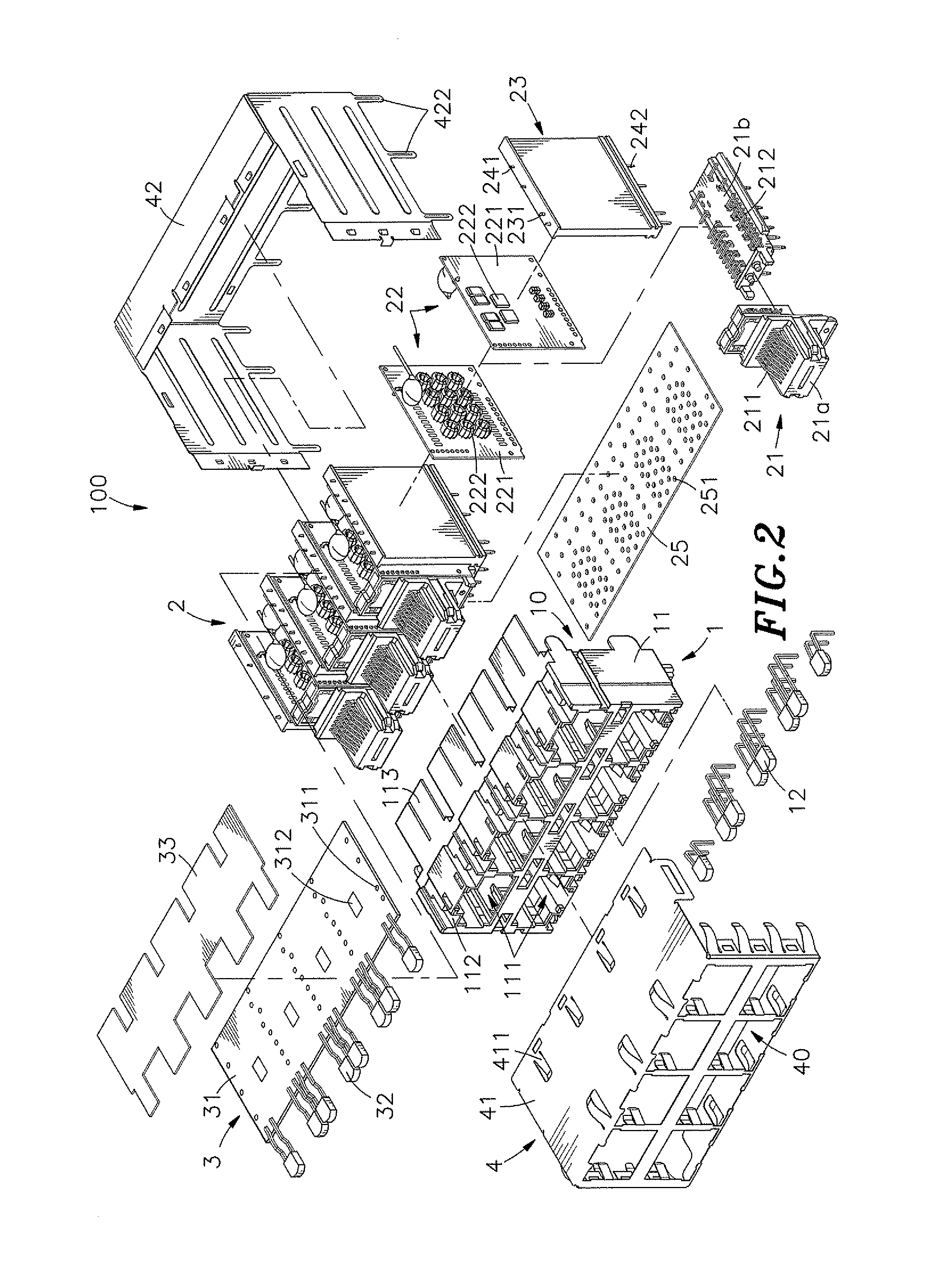
[0024]Referring to FIGS. 1, 2, 3 and 4, an elevational view, an exploded view, an exploded view viewed from another angle and a sectional rear side view in an enlarged scale of a stacked multi-port connector 100 in accordance with the present invention are respectively shown. The stacked multi-port connector 100 comprises a holder member 1, an electrical module 2, a light-emitting module 3, and an outer metal shield 4.

[0025]The holder member 1 comprises a frame base 11, an accommodation space 10 defined in the frame base 11 for accommodating the electric module 2, multiple rows of mating slots 111 defined in the front side of the frame base 11 at different elevations, a plurality of locating grooves 112 respectively and bilater...


PUM


Abstract

A stacked multi-port connector includes a holder member defining multiple rows of mating slots at different elevations, and an electrical module, which includes terminal blocks accommodated in the holder member and holding mating terminals in the mating slots, filter modules electrically coupled with the mating terminal and respectively attached to the terminal blocks, plate members respectively attached to the filter modules and holding therein conducting terminals, that are electrically coupled with light-emitting devices of a light-emitting module at the top side of the holder member, and metal shielding members respectively attached to the plate members between the conducting terminals and the circuit boards of the filter modules to protect signal transmission through the mating terminals from electromagnetic interference.

Description

BACKGROUND OF THE INVENTION[0001]1. Field of the Invention[0002]The present invention relates to electric connector technology and more particularly, to a stacked multi-port connector, which has metal shielding members respectively attached to plate members between conducting terminals, which are electrically coupled with light-emitting devices of a light-emitting module, and circuit boards of filter modules, protecting signal transmission through the mating terminals from electromagnetic interference and assuring a high level of signal transmission stability.[0003]2. Description of the Related Art[0004]Following fast development of computer technology, desk computers and notebook computers are well developed and widely used in different fields for different applications. It is the market trend to provide computers having high operating speed and small size. Further, network communication technology brings people closer, helping people to gather information about living, learning, w...

Claims


Application Information

Patent Timeline
Patent Type & Authority Patents(United States)
IPC IPC(8): H01R13/60
CPCH01R13/659H01R13/6633H01R13/717H01R24/64
Inventor CHEN, PO-JUNG
Owner U D ELECTRONIC CORP
Why Eureka
Try Eureka