Heat dissipation equipment of 5G base station

A technology for heat dissipation equipment and base stations, applied in the 5G field, can solve the problems of reduced convective heat dissipation effect of heat dissipation modules and equipment shells, more energy consumption of radio frequency chips, affecting signal transmission efficiency, etc., so as to reduce temperature and ensure signal transmission. Efficiency, the effect of enhancing the heat dissipation effect

Inactive Publication Date: 2020-07-17
沧州鹏举电子科技有限公司
View PDF0 Cites 2 Cited by
  • Summary
  • Abstract
  • Description
  • Claims
  • Application Information

AI Technical Summary

Problems solved by technology

[0006] In order to solve the above-mentioned technology, when the 5G base station is exposed to strong direct sunlight, the convective heat dissipation effect between the heat dissipation module and the equipment casing is reduced, and the temperature of the antenna bottom plate rises, resulting in more energy consumption for the radio frequency chip and affecting the signal transmission efficiency.

Method used


Image

  • Heat dissipation equipment of 5G base station
  • Heat dissipation equipment of 5G base station
  • Heat dissipation equipment of 5G base station

Examples


Embodiment 1

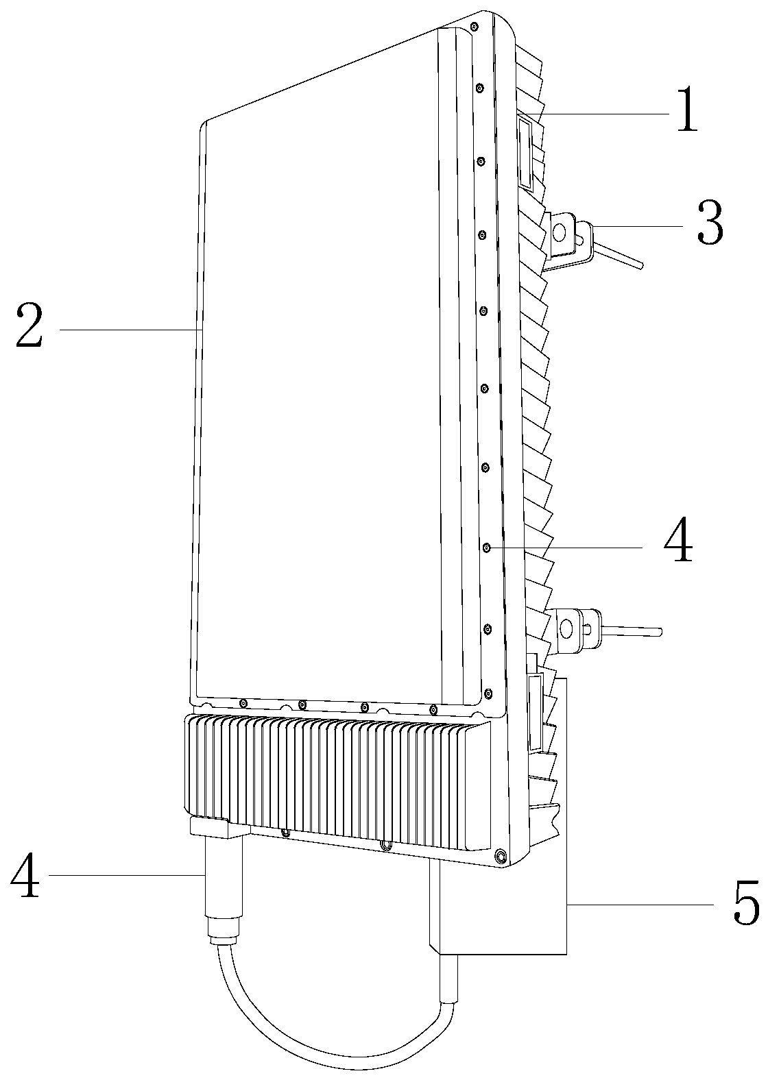
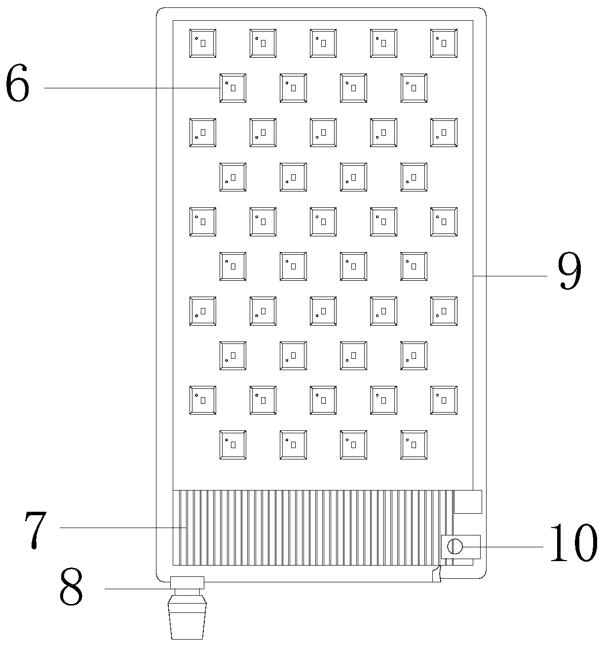
[0029] as attached figure 1 to attach Image 6 Shown:

[0030] The invention provides a heat dissipation device for a 5G base station, the structure of which includes a heat sink 1, a chassis 2, a connection buckle 3, a cable 4, a power supply box 5, a radio frequency chip 6, a power module 7, a power interface 8, an antenna base plate 9, and a fixed interface 10. The heat sink 1 is installed on the side of the chassis 2 and communicates with each other, the connecting buckle 3 is welded to the back of the chassis 2, the cable 4 is electrically connected to the bottom of the chassis 2, and the lower end of the power supply box 5 is electrically connected to the cable 4 , the radio frequency chip 6 is installed on the front end of the antenna base plate 9, the power supply module 7 is embedded and connected to the bottom of the chassis 2, the power interface 8 is matched with the bottom of the chassis 2 and electrically connected to the power supply module 7, the antenna base ...

Embodiment 2

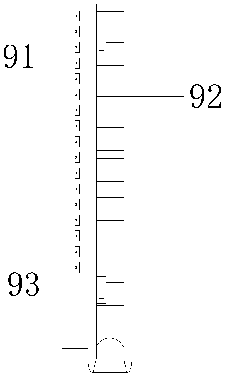
[0036] as attached Figure 7 to attach Figure 9 Shown:

[0037] Wherein, the side cover d3 is provided with a motor v1, a baffle v2, a gasket v3, and an air vent v4, the motor v1 is connected with the baffle v2, the gasket v3 is attached to the side of the baffle v2, and the The air passage hole v4 is perforated and connected with the gasket v3. There are eight air passage holes v4 in total. The baffle plate v2 has a narrow outside and wide inside structure. The connection port of the motor v1 is in a sealed structure, which is conducive to introducing air to enhance heat dissipation Effect.

[0038] Wherein, the baffle v2 is provided with a turbine z1, a sealing ring z2, a screw z3, and a gear z4, the turbine z1 is airtightly connected to the side of the sealing ring z2 through the screw z3, and the sealing ring z2 is in interference fit with the baffle v2 , the gear z4 is interference fit with the screw z3, the output end of the motor v1 is connected to the gear z4, the ...


PUM


Abstract

The invention discloses heat dissipation equipment of a 5G base station. The structure of the heat dissipation equipment comprises a cooling fins, a case, a connecting buckle, a cable, a power supplybox, a radio frequency chip, a power supply module, a power supply interface, an antenna bottom plate and a fixed interface., the The cooling fins are installed on the side face of the case and communicated with the case. Fan The fan operates, the operation, airflow enters the side wall of the temperature conduction layer through the cooling fins, and; heat is taken away through gas heat exchange;if the case is in a direct solar radiation state, the air convection heat dissipation effect is poor,; water-cooling heat dissipation can be carried out by the heat dissipation plate,; the vortex teeth and the capillary grooves scatter and throw out water flow into water mist in the rotating process, so thats and thus the water mist is attached to the threads on the heat dissipation cylinder, vaporization heat absorption is better carried out, the heat dissipation effect of the heat dissipation plate under strong direct solar radiation is enhanced, the temperature of the antenna bottom plateis reduced more quickly, the working energy consumption of a the radio frequency chip is reduced, and the signal transmission efficiency is ensured.

Description

technical field [0001] The invention belongs to the field of 5G, and more specifically, relates to a cooling device for a 5G base station. Background technique [0002] With the gradual arrival of the 5G era, more and more 5G base stations are established. The 5G signal frequency is high and the signal attenuation speed is fast. It is characterized by the integration of antenna and radio frequency unit, and the ceramic dielectric filter as the core component of the equipment. The radio frequency chip The array is showing a trend of densification. 5G base stations are generally built in high mountains. The heat dissipation of 5G equipment depends on laying heat dissipation modules under the antenna base plate, and adopts liquid cooling or air cooling to assist heat dissipation; [0003] Based on above-mentioned inventor's discovery, existing mainly exists following deficiency, such as: [0004] Due to the intensive requirements of the 5G base station RF chip array, the gap b...

Claims


Application Information

Patent Timeline
Patent Type & Authority Applications(China)
IPC IPC(8): H05K7/20
CPCH05K7/20709H05K7/20718H05K7/208
Inventor 何水远
Owner 沧州鹏举电子科技有限公司
Why Eureka
Try Eureka