Airplane lavatory filtering system device

Inactive Publication Date: 2013-06-11
CM2 ENTERPRISES
View PDF13 Cites 20 Cited by
  • Summary
  • Abstract
  • Description
  • Claims
  • Application Information

AI Technical Summary

Benefits of technology

[0005]The frame is mounted to the inside surface of a lavatory door covering a vent louver. The frame is secured to the door by adhesive strips attached to the lower surface of the flanges. A filter dimensioned to fit within the cham

Problems solved by technology

While air filtering devices for commercial air tra

Method used


Image

  • Airplane lavatory filtering system device
  • Airplane lavatory filtering system device
  • Airplane lavatory filtering system device

Examples


Embodiment Construction

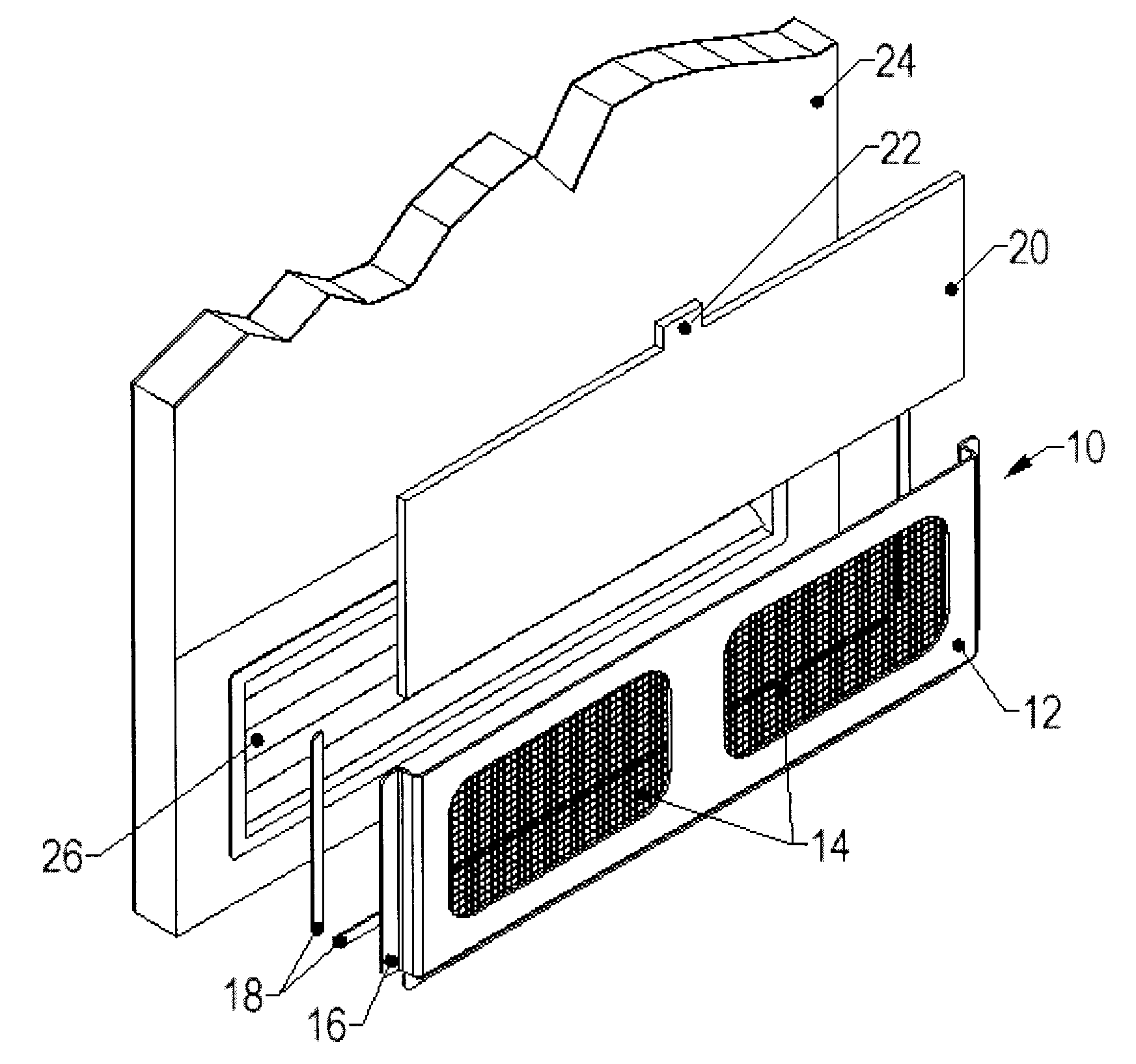
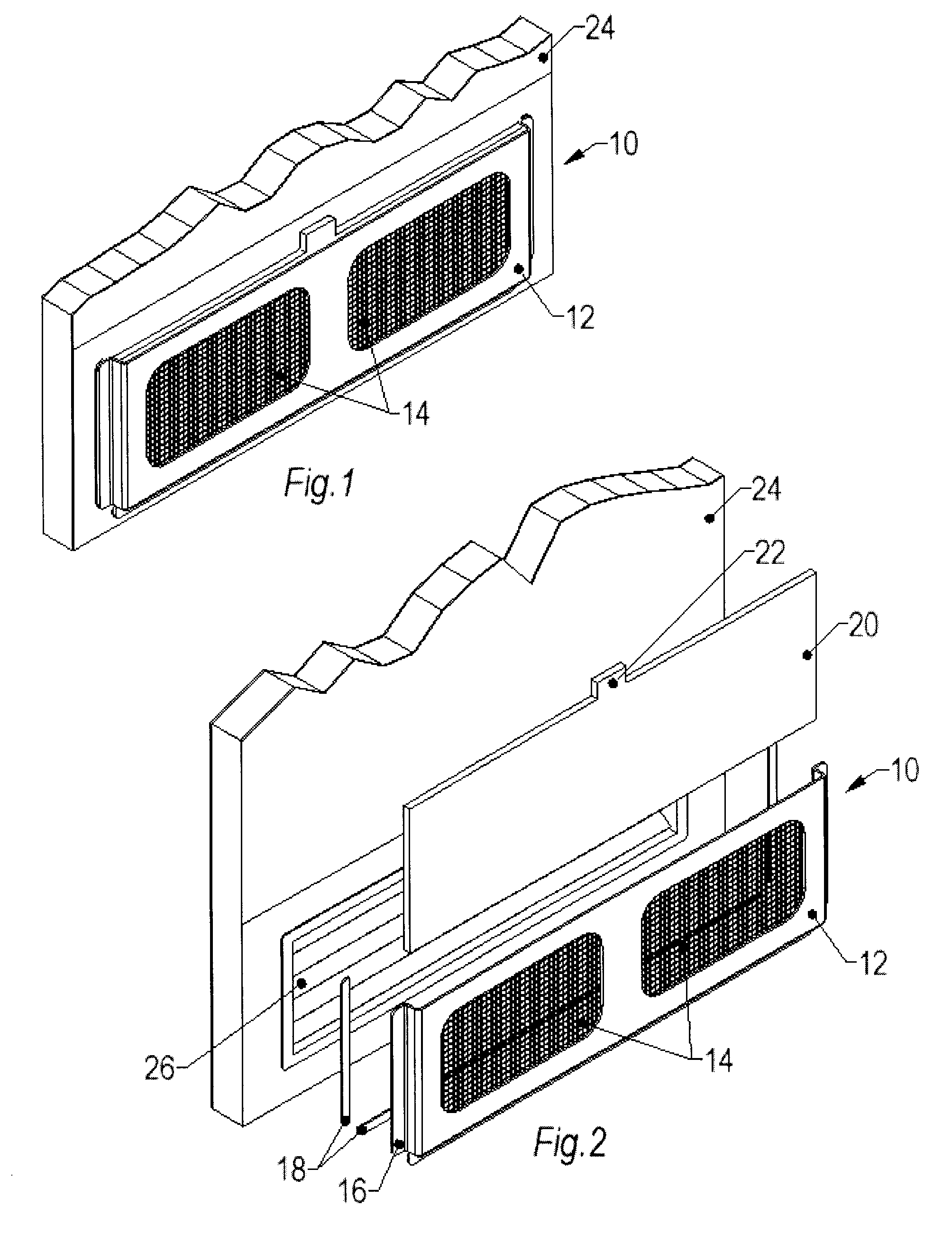
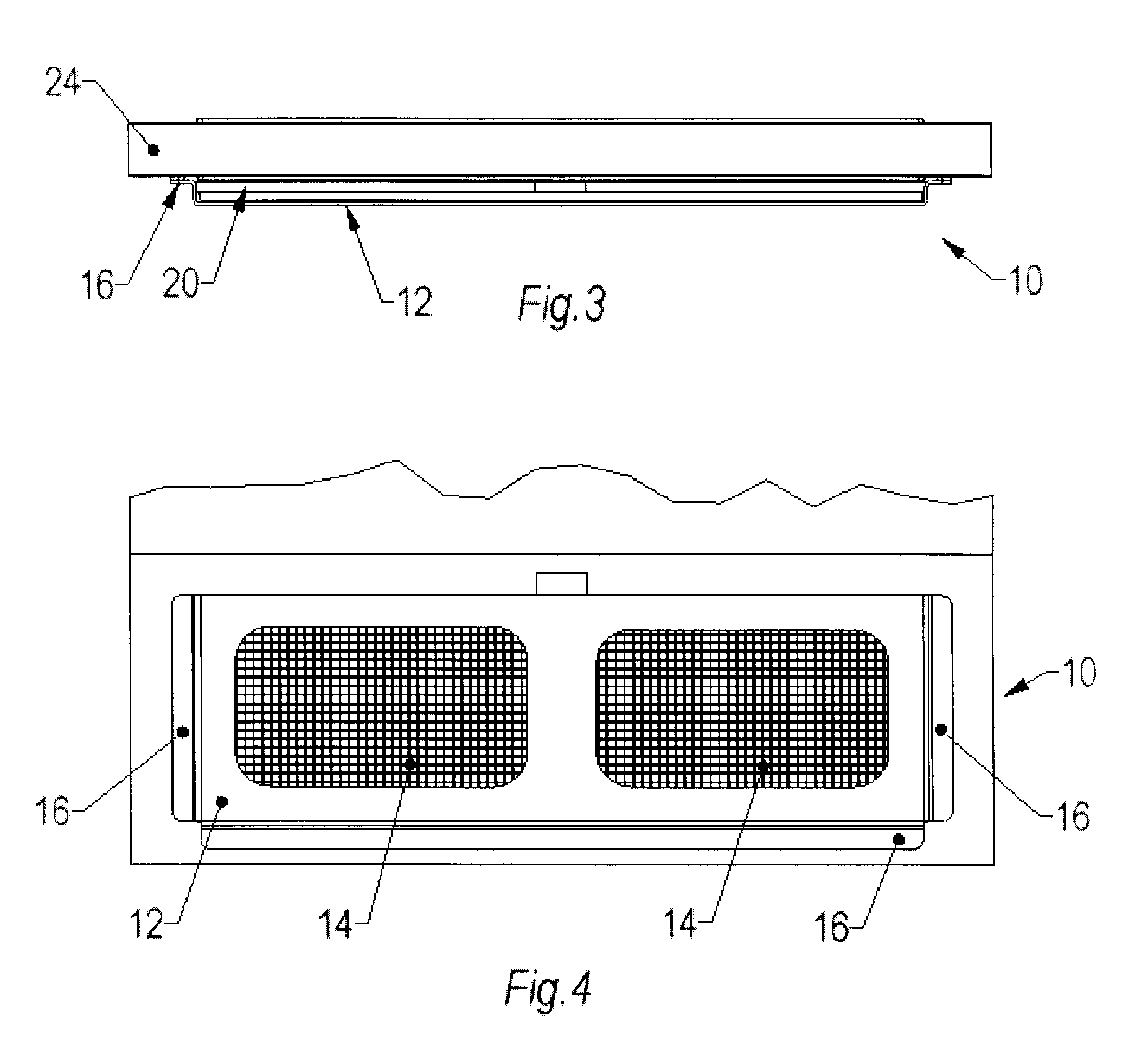
[0015]In reference to FIGS. 1 and 2, the invention, denoted generally by reference numeral 10, is shown mounted to a lavatory door 24 of an airplane. The device 10 comprises a frame 12 having a pair of transverse side walls, each with a first end and a second end, with inner and outer surfaces, and each defining the width of the frame 12, a longitudinal bottom wall integrally formed perpendicularly with the first ends of the side walls, with an inner and outer surface, defining the length of the frame 12, and a front wall with passages defined therethrough. Flanges 16, having an upper surface and a lower surface, depend outwardly perpendicularly from the side walls and bottom wall. The frame 12 and flanges 16 are formed of resilient material, preferably aluminum or impact resistant plastic. The inner surfaces of the walls define a chamber and there is an opening defined at the second end of the side walls of the frame 12.

[0016]Panels 14 formed of mesh material, with air pathways the...


PUM


Abstract

The present invention an airplane air filtering system device comprised of a frame having flanges, including means to mount to the inside surface of a lavatory door oriented with vent louvers. The frame is preferably mounted to the door with adhesive strips. A replaceable filter with a grasping tab is placed within the frame. As the toilet in the airplane lavatory is flushed, vacuum action causes air outside of the lavatory to be pulled through the filter.

Description

BACKGROUND OF INVENTION[0001]The present invention relates to an airplane air filtering system device comprised of a frame for a replaceable filter mounted to the inside surface of a lavatory door behind louvers.[0002]While air filtering devices for commercial air travel are available the air filters are inefficient. The present invention is comprised of a housing for a replaceable filter mounted to the inside surface of an airplane lavatory door behind a vented louver. The housing is mounted with adhesive strips. As the toilet in the airplane lavatory is flushed vacuum action causes air outside of the lavatory to be pulled through the filter. A grasping tab allows the filter to be easily replaced. Fragrance in the filter refreshes the inside area of the lavatory.SUMMARY OF THE INVENTION[0003]The general purpose of the present invention, which will be described subsequently in greater detail, is to provide a new and improved air filtering system for lavatories of airplanes, trains o...

Claims


Application Information

Patent Timeline
IPC IPC(8): B01D46/00
CPCB01D46/10B01D46/2411
Inventor HOBBS, CLIFF
Owner CM2 ENTERPRISES
Why Eureka
Try Eureka