Method for recycling energy in a blow moulding machine for blow moulding containers

a technology of blow moulding machine and energy recycling, which is applied in the field of method for recycling the pneumatic energy of discharge air, can solve the problems of reducing the efficiency of the air blowing machine, so as to achieve the effect of improving efficiency

Active Publication Date: 2013-06-11
SIPA SOCIETA INDUSTRIALIZZAZIONE PROGETTAZIONE E AUTOMAZIONE SPA
View PDF6 Cites 0 Cited by
  • Summary
  • Abstract
  • Description
  • Claims
  • Application Information

AI Technical Summary

Benefits of technology

[0012]It is a main object of the present invention to optimize the method for recycling the pneumatic energy of discharge air coming from the blowing cavities of moulding machines for plastic material containers, so as to obtain a better efficiency in virtue of a predetermined selection of shearing pressure values.
[0013]A further object of the invention is to make an alternative system for recycling the pneumatic energy of the discharge air, coming from the blowing cavities of moulding machines for plastic material containers, which allows the recycling of blowing air making it available at least one predetermined pressure either directly to the primary air tank or directly to the secondary air tank or to at least one specific recycling tank.
[0031]the high simplicity and cost-effectiveness of the plant, which does not require the use of dedicated tanks for recycling the blowing air, with corresponding systems and adjusting devices, except for those normally used for the primary and secondary air;
[0032]the use of an on / off valve arranged upstream of the pressure adjuster on the feeding line of the primary air tank to better manage the direct recycling of the air in the primary air tank;
[0033]less invasiveness during the step of recycling with respect to the total availability of the blowing time and thus a lower impact on the total process window, being the shearing pressure higher than the pressure of standard recycling methods;
[0034]the choice of the shearing pressure is calibrated so as to balance the volume of recycled air with respect to that used as primary air, and thus to reduce the pressure oscillation in the primary air tank.

Problems solved by technology

At the end of the blow moulding operation, the remaining pneumatic energy of the compressed air, coming from the blowing cavities, is generally lost.
Given the non-negligible residual pressure of this blowing air and the continuous operation of this machinery, not recycling said pneumatic energy implies a considerable energy waste in the energy balance of these machines.

Method used


Image

  • Method for recycling energy in a blow moulding machine for blow moulding containers
  • Method for recycling energy in a blow moulding machine for blow moulding containers
  • Method for recycling energy in a blow moulding machine for blow moulding containers

Examples


first embodiment

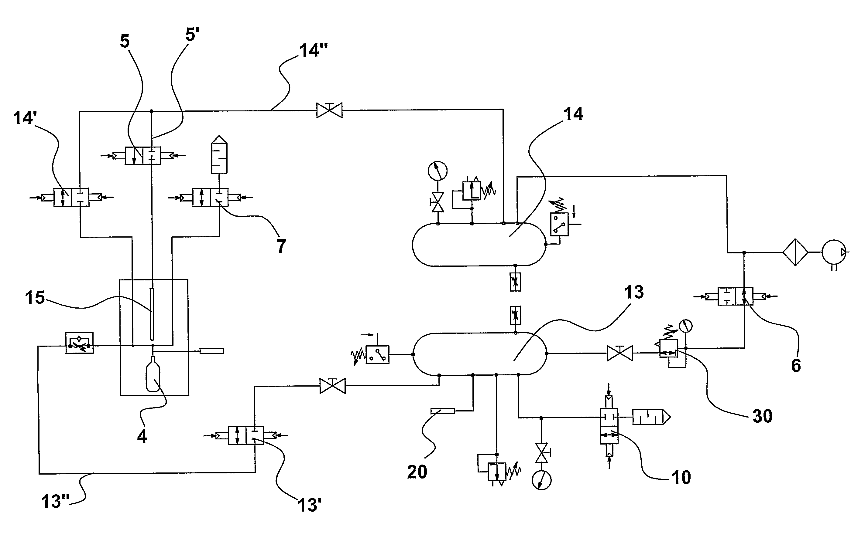
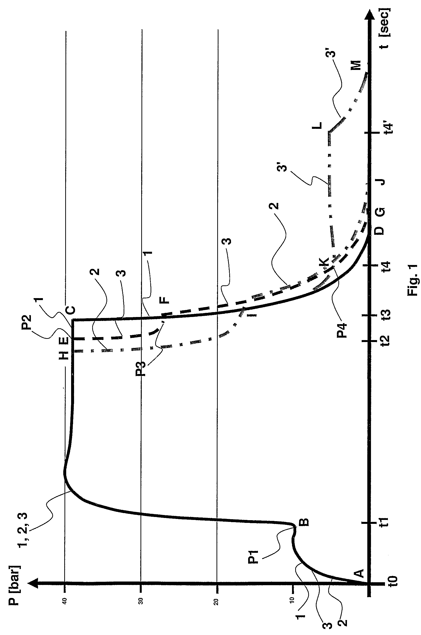
[0047]Referring to FIG. 1, the pressure profiles in blowing cavities for plastic containers are diagrammatically shown in a comparative manner, the profiles corresponding to:[0048]i) a standard blowing process with use of primary air plus secondary air, without air recycling: profile A-B-C-D, indicated by the curve having reference number 1;[0049]ii) a blowing process with recycling of the blowing air according to the state of the art: profile A-B-H-I-J, indicated by the curve having reference number 2;[0050]iii) the blowing process with air recycling at a medium pressure according to the invention: profile A-B-E-F-G indicated by the curve having reference number 3.

[0051]The recycling process of the invention for recycling the blowing air at a medium pressure is carried out as follows.

[0052]Compressed air at low pressure P1, about 10 bars, the so-called primary air, is blown into the parisons which are at a temperature such as to allow an expansion thereof to adapt to the inner prof...

second embodiment

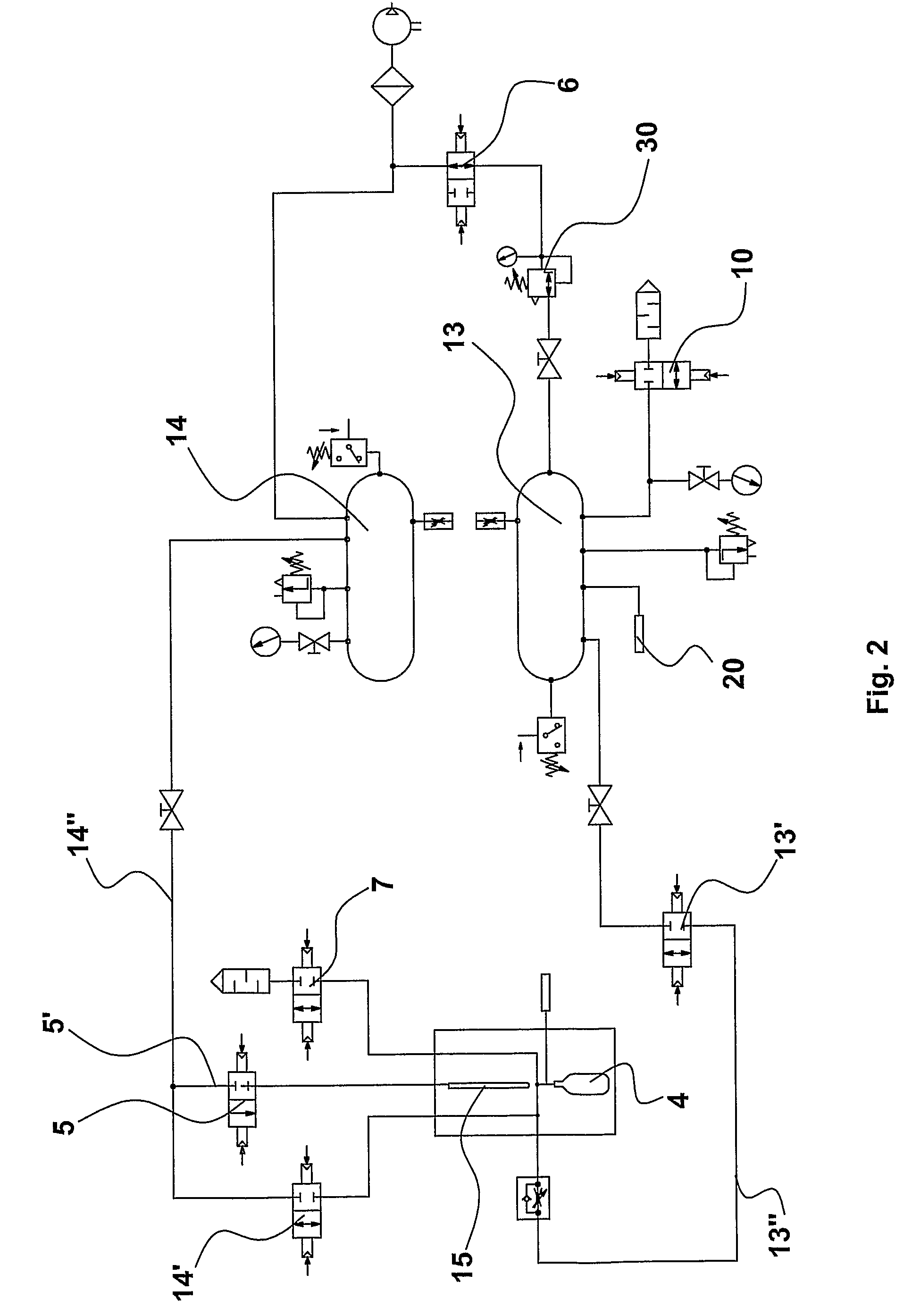
[0110]With reference to FIG. 3, the pressure profiles in blowing cavities for plastic containers are diagrammatically shown in a comparative manner, the profiles corresponding to:[0111]i) the standard blowing process using primary air plus secondary air, without air recycling: profile A-B-C-D, indicated by the curve having reference number 1;[0112]ii) the blowing process with recycling of blowing air of the state of the art: profile A-B-H-I-J, indicated by the curve having reference number 2;[0113]iii) the blowing process with air recycling at a medium pressure according to the invention: profile A-B-E′-E-F-F′-G, indicated by the curve having reference number 31.

[0114]The blowing air recycling process, in this second embodiment, provides a double-recycling at medium and low pressure and is performed as follows.

[0115]Compressed air at low pressure of about 10 bars, the so-called primary air, is blown in the parisons, which are at a temperature such as to allow an expansion thereof to...


PUM

PropertyMeasurementUnit
pressureaaaaaaaaaa
pressureaaaaaaaaaa
pressureaaaaaaaaaa

Abstract

A method for recycling energy and related blow molding machine—for blow molding plastic material containers including a recycling system for recycling the pneumatic energy of the discharge air coming from the blowing cavities of said machine, capable of recycling the discharge air making it available at a given pressure for a subsequent blowing in a cavity.

Description

FIELD OF THE INVENTION[0001]The present invention relates to a method for recycling the pneumatic energy of discharge air, coming from the blowing cavities of moulding machines for plastic material containers, for instance bottles made of PET, and to a corresponding plant.STATE OF THE ART[0002]There are known plants or systems for recycling energy from air or other pressurized gases, used for various industrial processes in the related plants. An example of such systems is described in document U.S. Pat. No. 4,488,863 in which there is disclosed a system for recycling the blowing air for plastic containers comprising a plant, specifically formed by pneumatic valves and sensors, capable of tracking the compressed air pressure profile during the degassing step of the cavities and making the air available at a low pressure to be used again.[0003]In the production of bottles or other plastic material containers, among which nowadays those made of PET are extremely widespread, the blow m...

Claims


Application Information

Patent Timeline
Patent Type & Authority Patents(United States)
IPC IPC(8): B29C49/62
CPCB29C49/783B29C49/06B29C49/12B29K2067/00B29C49/66B29C49/4823Y02P70/10B29C49/42109B29C49/42855B29C2949/0715B29C49/6605B29C2049/7831B29C2049/7832B29C2049/7833B29C2049/7835
Inventor ZOPPAS, MATTEOPITTARI, GIAMPIETROALTOE', MIRKOPOLENTES, MORIS
Owner SIPA SOCIETA INDUSTRIALIZZAZIONE PROGETTAZIONE E AUTOMAZIONE SPA
Why Eureka
Try Eureka