Elastic electric contact terminal

a contact terminal and elastic technology, applied in the direction of conductors, non-insulated conductors, coupling device connections, etc., can solve the problems of reflow soldering defects, contact terminal needs bending, and it is difficult to manufacture elastic electric contact terminals of about 1.5 mm or less in height, etc., to achieve high elasticity, electrical conductivity, and recovery rate. small

Active Publication Date: 2013-06-11
JOINSET +1
View PDF10 Cites 15 Cited by
  • Summary
  • Abstract
  • Description
  • Claims
  • Application Information

AI Technical Summary

Benefits of technology

[0019]An object of the present invention is to provide a low-height elastic electric contact terminal having high elasticity, recovery rate, and electrical conductivity and requiring a small pressing force.
[0020]Another object of the present invention is to provide a low-height elastic electric contact terminal having a high recovery rate by maximizing an exposed area of a side surface of an elastic core, and requiring a small pressing force.
[0022]A still another object of the present invention is to provide a low-height elastic electric contact terminal conveniently mounted to a facing object and easily manufactured at a low manufacturing cost.
[0023]A yet another object of the present invention is to provide a low-height elastic electric contact terminal improved in solder strength with respect to a facing object.
[0024]Yet still another object of the present invention is to provide a low-height elastic electric contact terminal facilitating surface mounting by pick-and-place and reflow soldering by a solder paste.
[0026]Still yet another object of the present invention is to provide a low-height elastic electric contact terminal minimizing solder rise occurring at lateral sides of a metal layer and affecting the elasticity, recovery rate, and required pressing force.

Problems solved by technology

However, the metal sheet solely constructing the elastic electric contact terminal needs bending to obtain elasticity.
Therefore, it is hard to manufacture an elastic electric contact terminal of about 1.5 mm or less in height.
Therefore, the elastic electric contact terminal may be easily moved by air supplied for surface mounting, which may cause defects during reflow soldering.
In addition, if pressed by more than a predetermined degree of force, the elastic electric contact terminal loses the elasticity and remains in the pressed form or breaks.
That is, a plurality of expensive molds are necessary to manufacture elastic electric contact terminals in various structures and sizes.
However, with the above structure, an elastic electric contact terminal is hard to have a smaller size, more specifically, within a width of about 3.0 mm and a height of about 2.2 mm.
Therefore, it is difficult to thoroughly enclose the insulating foam rubber core 10 by the heat-resistant polymer film 30 which includes the metal layer 40 on the rear side thereof.
Also, it is difficult to dispose both ends of the heat-resistant polymer film 30 at a lower central surface of the elastic electric contact terminal.
When the rubber coating layer 20 is cured on the metal layer 40, soldering of the metal layer 40 may be poorly performed, thereby reducing the solder strength.
Also, when the elastic electric contact terminal has a low height, the weight is reduced and it becomes hard to obtain reliable flatness of the lower surface.
In this case, the elastic electric contact terminal may be displaced by air supplied during surface mounting and reflow soldering, resulting in reflow soldering defects.
Such a material having a high electrical resistance is inadequate for an electrical contact because it increases power consumption and a contact resistance.

Method used


Image

  • Elastic electric contact terminal
  • Elastic electric contact terminal
  • Elastic electric contact terminal

Examples


first embodiment

1. First Embodiment

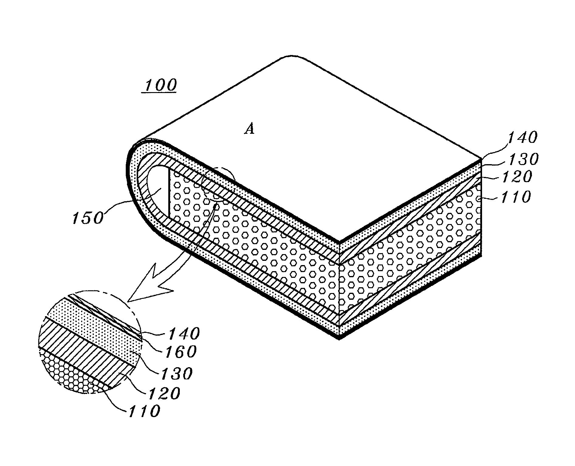
[0057]FIG. 2 shows an elastic electric contact terminal 100 according to a first embodiment of the present invention.

[0058]The elastic electric contact terminal 100 includes an insulating elastic core 110 made of foam rubber, an insulating non-foam rubber coating layer 120, and a heat-resistant polymer film 130 including a metal layer 140 integrally formed with a rear side thereof.

[0059]Referring to FIG. 2, the heat-resistant polymer film 130 including the metal layer 140 is adhered through the insulating non-foam rubber coating layer 120 to enclose upper and lower surfaces and any one side surface of the insulating elastic core 110. The other side surfaces of the insulating elastic core 110 are exposed.

[0060]A part of the heat-resistant polymer film 130, which encloses the side surface of the insulating elastic core 110, is curved into an arc. According to the present embodiment, at the curved part, only the heat-resistant polymer film 130 is in adhesive contact ...

second embodiment

2. Second Embodiment

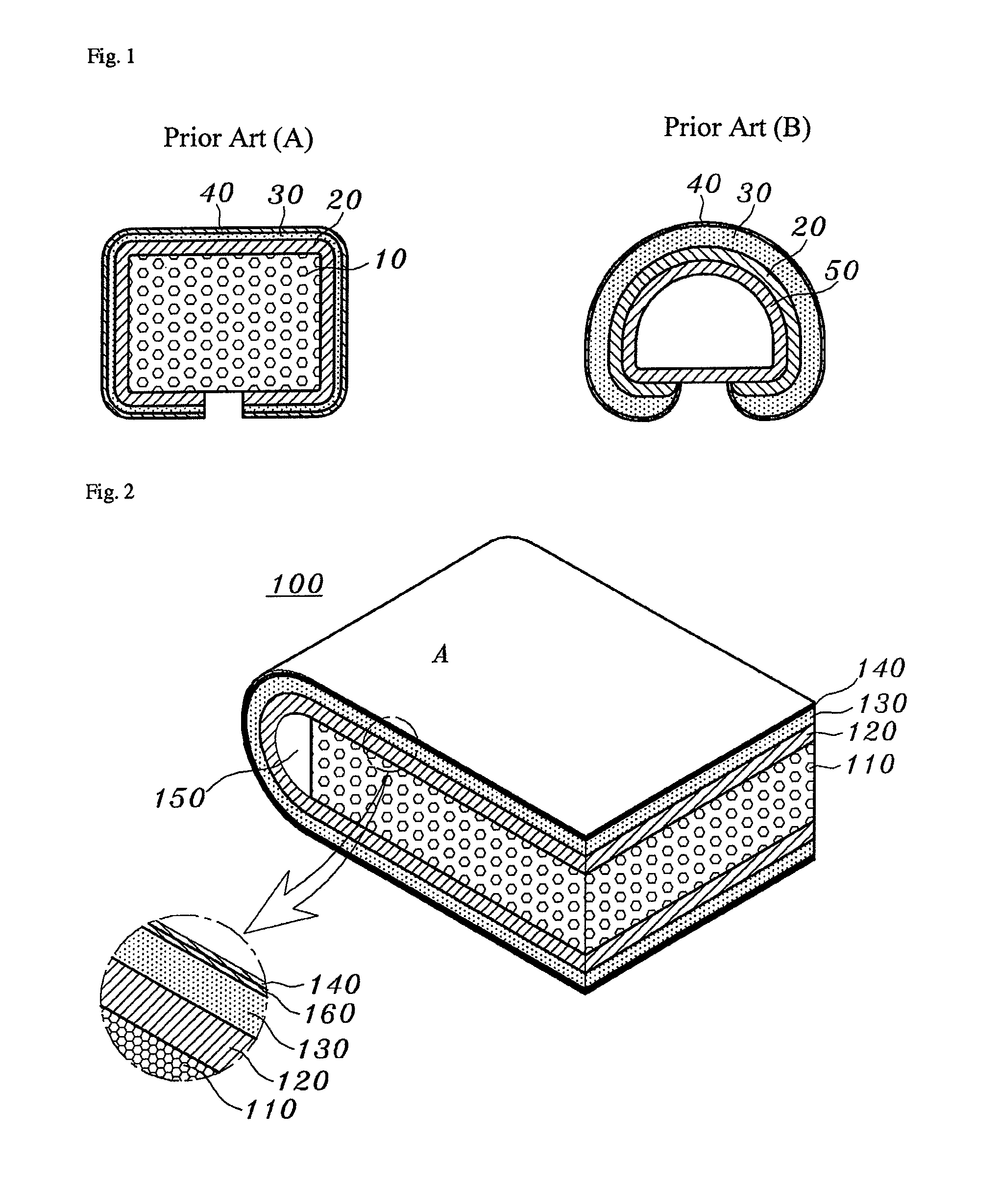
[0122]FIG. 3 shows an elastic electric contact terminal 200 according to a second embodiment of the present invention.

[0123]Referring to FIG. 3, a solderable metal film 270 is adhered to an outer surface of a metal layer 240 at a position corresponding to a lower surface of an insulating elastic core 210.

[0124]The electrically conductive adhesive 260 may be any one of an electrically conductive silicon rubber adhesive, an electrically conductive epoxy adhesive, and a solder. The solder is recommended to reduce the electrical resistance.

[0125]It is exemplary that the solderable metal film 270 is made of any one of Cu and a Cu alloy to a thickness of about 0.01 mm to 0.08 mm.

[0126]It is exemplary that a surface of the solderable metal film 270 is plated with any one of Sn, Ag, and Au to prevent corrosion and facilitate the soldering.

[0127]It is exemplary that the metal film 270 has a similar width to the elastic electric contact terminal 200 so that the soldering u...

third embodiment

3. Third Embodiment

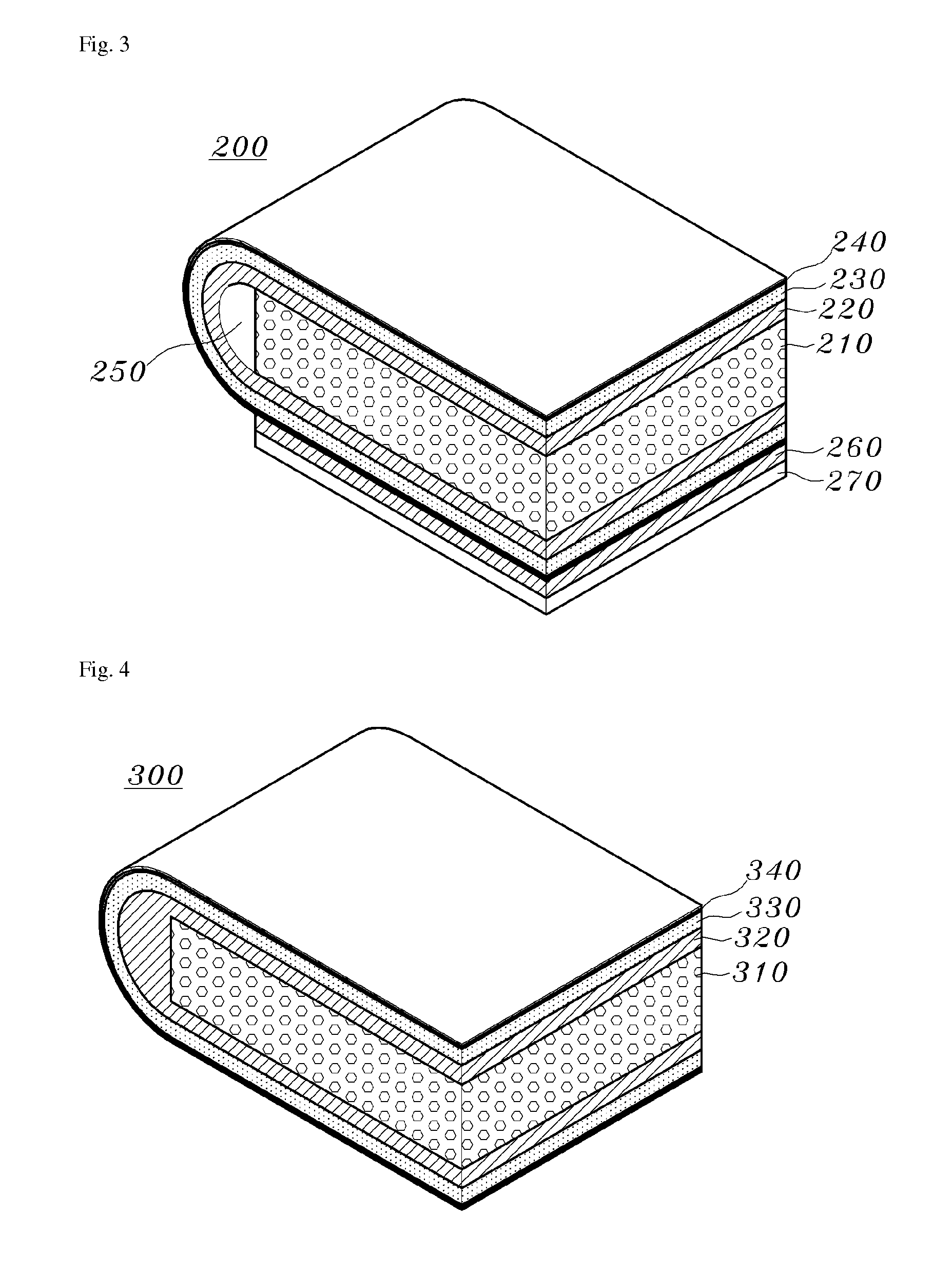
[0131]FIG. 4 shows an elastic electric contact terminal 300 according to a third embodiment of the present invention.

[0132]Referring to FIG. 4, a non-foam rubber coating layer 320 is interposed and adhered between an insulating elastic core 310 and a heat-resistant polymer film 330 which includes a metal layer 340 formed thereon. The heat-resistant polymer film 330 encloses the insulating elastic core 310, being curved into an arc at one side of the insulating elastic core 310.

[0133]In comparison with the first embodiment shown in FIG. 2, the third embodiment does not have the space 150 of FIG. 2 because the side surface of the insulating elastic core 310 is adhered to the non-foam rubber coating layer 320.

[0134]The insulating elastic core 310 has a lower hardness and a higher recovery rate than the non-foam rubber coating layer 320.

[0135]According to this structure, since the heat-resistant polymer film 330 integrally formed with the metal layer 340 is curved int...


PUM

PropertyMeasurementUnit
thicknessaaaaaaaaaa
heightaaaaaaaaaa
heightaaaaaaaaaa

Abstract

An elastic electric contact terminal including an elastic foam core having a sheet form, a non-foam rubber coating layer adhered to upper and lower surfaces of the elastic foam core and continued along any one side surface of the elastic foam core, and a heat-resistant polymer film, one side of which is adhered to the non-foam rubber coating layer in an enclosing manner and the other side of which is integrally formed with a metal layer.

Description

FIELD OF THE INVENTION[0001]The present invention relates to an elastic electric contact terminal, and more particularly, to an elastic electric contact terminal capable of electrically, mechanically, and elastically connecting an electrically conductive object with a conductive pattern formed on a printed circuit board (PCB) which are facing each other. In addition, the present invention relates to a small-sized elastic electric contact terminal surface-mounted with a minimum height of reflow soldering.DESCRIPTION OF THE RELATED ART[0002]Elastic electric contact terminals are used to electrically and elastically connect electrically conductive objects and conductive patterns of a printed circuit board (PCB) which are facing respectively or alternately.[0003]Besides, the elastic electric contact terminal may also be used to as any of an electrical ground, an electrical contact, an electrical adhesive tape, and an electromagnetic interference (EMI) gasket.[0004]For such purposes, it ...

Claims


Application Information

Patent Timeline
Patent Type & Authority Patents(United States)
IPC IPC(8): H01B5/00
CPCH01R13/2414H01R12/57H01R13/6584
Inventor KIM, SUN-KI
Owner JOINSET
Why Eureka
Try Eureka