
Dual mode vibrator

a vibrator and dual-mode technology, applied in the direction of motor/generator/converter stopper, dynamo-electric converter control, instruments, etc., can solve the problems of vibration signal monotony, vibration units deviating from the predetermined position, frequency change in current or vibration reduction, etc., to improve product reliability.

Inactive Publication Date: 2013-06-11
EM TECHNOLOGY CO LTD
View PDF77 Cites 8 Cited by
  • Summary
  • Abstract
  • Description
  • Claims
  • Application Information

AI Technical Summary

Benefits of technology

The present invention provides a dual mode vibrator that can provide a variety of vibrations and enhance the reliability of the product. The vibrator includes a housing, a coil, two vibrating units, elastic members, and prevention means to prevent deformation of the elastic members. The vibrating units vibrate in response to different frequency bands of current applied to the coil. The invention prevents plastic deformation of the elastic members and ensures that the vibrating units can be positioned at predetermined positions, enhancing the reliability of the product.

Problems solved by technology

The conventional vibration generating device is formed with only one vibrating unit for generating the vibration, such that a vibration signal is monotonous.
In the conventional dual mode vibrator, the vibrating units are supported only by the spring, such that the vibrating units may deviate from a predetermined position at a predetermined distance or more by shock and other outside factors, whereby the spring is plastic-deformed by the vibrating units, resulting in the vibrating units deviating from the predetermined position.
In that case, frequency change in the current or reduction in vibration may be incurred to decrease reliability of the product.

Method used


Image

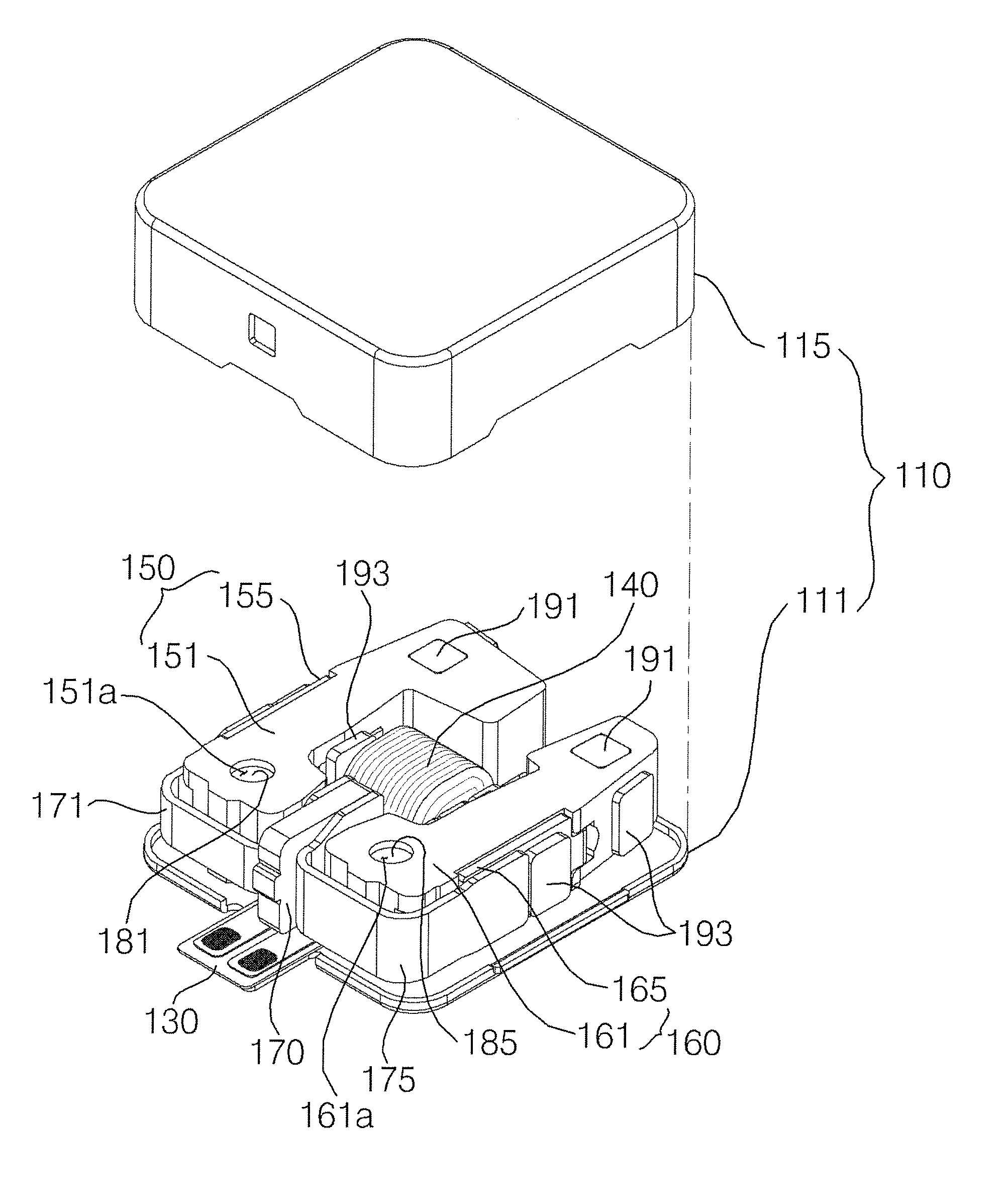
  • Dual mode vibrator
  • Dual mode vibrator
  • Dual mode vibrator

Examples


Embodiment Construction

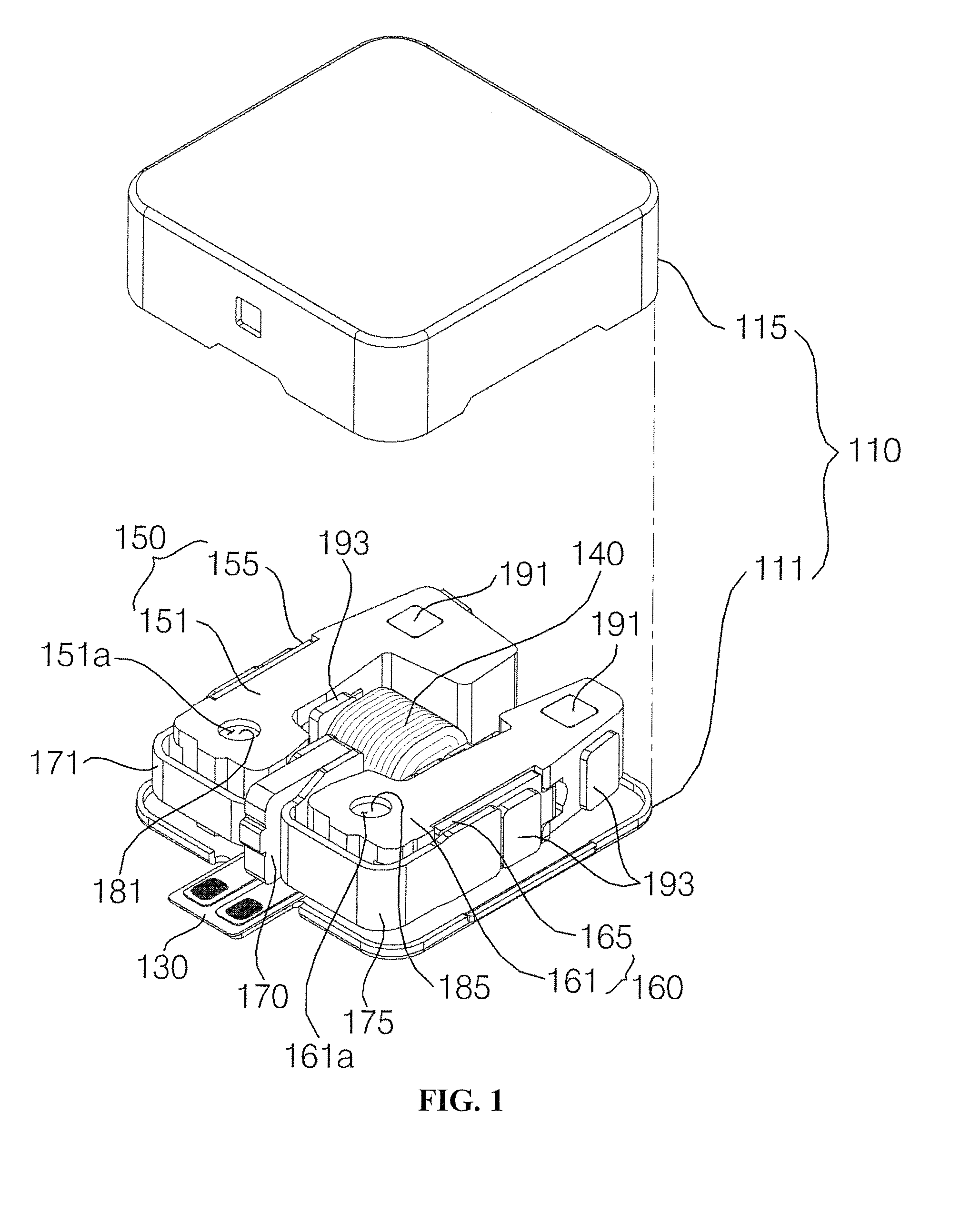
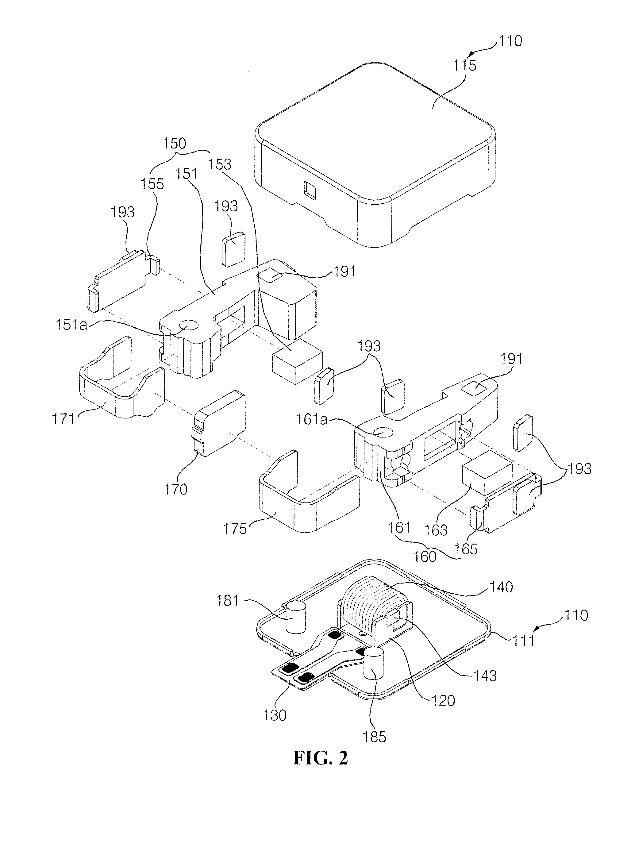
[0025]A dual mode vibrator according to exemplary embodiments of the present disclosure will be described in detail with reference to the accompanying drawings.

[0026]The suffixes ‘module’, ‘unit’, ‘portion’ and ‘part’ may be used for elements in order to facilitate the disclosure. Significant meanings or roles may not be given to the suffixes themselves and it is understood that the ‘module’, ‘unit’, ‘portion’ and ‘part’ may be used together or interchangeably.

[0027]FIG. 1 is a perspective view of a dual mode vibrator according to an exemplary embodiment of the present disclosure, FIG. 2 is an exploded perspective view of a dual mode vibrator according to an exemplary embodiment of the present disclosure, and FIG. 3 is a plain cross-sectional view in which a case of a dual mode vibrator is removed according to an exemplary embodiment of the present disclosure.

[0028]As illustrated in the figures, the dual mode vibrator is installed at a product such as a mobile terminal, and is provi...


PUM


Abstract

A dual mode vibrator is disclosed. There are available two vibrating units to enable obtainment of a variety of vibrations. Each lateral portion of the first and second vibrating units respectively supported by the first and second elastic members is supported by the first and second support bars secured at the housing for rotatable installation. Therefore, although the first and second vibrating units may rotate about the first and second support bars, the first and second vibrating units are not allowed to deviated or disengaged from the first and second support bars, whereby the plastic deformation of the first and second elastic members is prevented, and the first and second vibrating units can be positioned at predetermined positions at all times to enhance reliability of product. Furthermore, each lateral portion of the first and second vibrating units is respectively supported by the first and second elastic members while the other lateral portions of the first and second vibrating units are restrained by a stopper at a predetermined distance or more.

Description

CROSS-REFERENCE TO RELATED APPLICATIONS[0001]This application claims the benefit under 35 U.S.C. §119 of Korean Patent Application Nos. 10-2009-0048573,filed on Jun. 2, 2009, and 10-2009-0048576, filed on Jun. 2, 2009, which are hereby incorporated by reference in their entirety.BACKGROUND OF THE INVENTION[0002]1. Field of the Invention[0003]The present disclosure relates to a dual mode vibrator.[0004]2. Description of Related Art[0005]Generally, mobile terminals are embedded with a signal generating device such as a sound generating device or a vibration generating device announcing arrival of an arrival signal.[0006]The conventional vibration generating device is formed with only one vibrating unit for generating the vibration, such that a vibration signal is monotonous.[0007]A dual mode vibrator provided with two vibrating units has been developed in order to obtain various types of vibrations and differentiated vibration signals.[0008]The dual mode vibrator is configured in such...

Claims


Application Information

Patent Timeline
Patent Type & Authority Patents(United States)
IPC IPC(8): H04B3/36
CPCH02K33/06H02K16/02
Inventor AN, SUNGHWAN
Owner EM TECHNOLOGY CO LTD
Learn More