Firearm maintenance system

a maintenance system and firearm technology, applied in the field of firearm maintenance system, can solve the problems of incomplete overhaul of the firearm, unnecessary maintenance of little used firearms, and based preventive maintenance methods, so as to prolong the life and the life of the shot counter device, and the current draw is reduced.

Inactive Publication Date: 2013-06-18
HARPER JOHN
View PDF14 Cites 11 Cited by
  • Summary
  • Abstract
  • Description
  • Claims
  • Application Information

AI Technical Summary

Benefits of technology

[0028]In the most preferred embodiment of the present invention, the means for comparing is provided by a laptop computer programmed with a weapon maintenance algorithm. The laptop and algorithm provide a means for timely advising maintenance personnel when a component part is nearing or has reached the end of its useful life.
[0030]The maintenance system of the present invention also includes means for updating maintenance data stored in the memory by transmitting updated maintenance data into the memory. After a maintenance operation is performed on the firearm, such as repair or replacement of a component, the operator inputs updated maintenance data reflecting the operation. In the most preferred embodiment of the present invention, the infrared communication devices are used to transfer the updated maintenance data. This allows the entire firing history and maintenance history of a weapon to be stored in memory, so that by placing the memory on the firearm, the entire history of the weapon is resident thereon. This eliminates the need to store firearm data somewhere else to be accessible and modifiable by referring to the firearm's identification code or serial number.
[0031]The firearm mounted device for counting shots of the firearm comprises an inertia switch mounted on the firearm, a processor mounted on the firearm to receive a signal from the inertia switch and increment a shot count value each time a shot is fired, memory mounted on the firearm to store the shot count value, an infrared communication card mounted on the firearm transmitting data to and from the memory, a battery providing power for the processor, memory and communication card, and an epoxy encasing of the inertia switch, processor, memory, infrared communication card and battery wherein an epoxy housing is affixed to the firearm. In the most preferred embodiment of the present invention, the battery is not supplying power until receiving a signal from the inertia switch or the communication card to minimize the current draw on the battery to extend its life and the life of the shot counter device.

Problems solved by technology

Both the calendar based preventive maintenance method and usage based preventive maintenance method have drawbacks.
First, both generally result in complete overhauls of the firearm when the maintenance is performed, even though some components have longer useful lives than others and do not need to be repaired or replaced.
In addition, calendar based preventive maintenance systems result in unnecessary maintenance being performed on little used firearms while missing necessary maintenance on heavily used firearms.
A preventive maintenance system for a firearm that is dependent on tracking the usage of the firearm is costly because it necessitates the addition and use of a shot counter.
In addition, such preventive maintenance systems are also costly because the maintenance that is performed, based upon usage, is generally a complete overhaul, repair or replacement, of all of the components of the firearm prone to wear and tear.
The individual components are not monitored or tracked, so components with relatively long useful lives are unnecessarily repaired or replaced, an inefficiency even in the usage based preventive maintenance system.
The importance of an effective and efficient preventive maintenance system for maintaining firearms cannot be overstated, particularly for large entities such as police departments or military units wherein life and death depend on the reliable operation of firearms.
While it is most important to such entities, it is also most difficult to implement a preventive maintenance system for such a large group of weapons because a large amount of data (shot counting for each firearm) must be accurately maintained.
If not diligently implemented, the reliability of all firearms is suspect and the system fails.
The tracking of a weapon, and the maintenance history of the weapon, becomes an enormous and time consuming task when large numbers of weapons are involved.
Tracking all of the maintenance steps performed on a weapon and attaching it to the weapon's serial number is complex when weapons are put into service in one location, taken out of service and sent somewhere else for maintenance, repaired, and put back into service in another location.
The logistics and data entry requirements are only made more complex when this process is repeated.
Any errors in data entry, such as in weapon or shot counter serial number, maintenance history, etc., will compromise the whole system and will probably only be identified if the weapon fails, a potentially catastrophic occurrence.
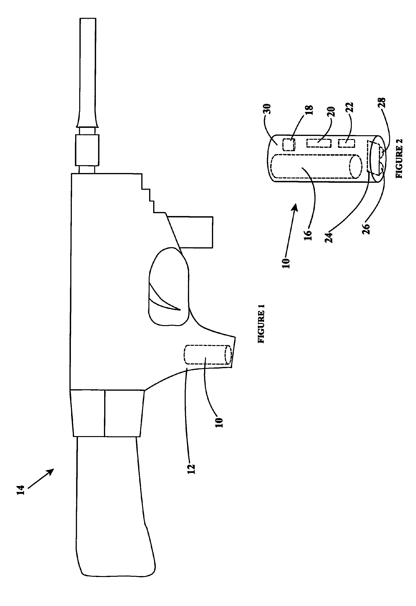
For the preferred usage based preventive maintenance system, the first obstacle is to provide a reliable device and method for counting how many shots are fired.
Failure of the power supply results in a failure of the shot counter and, effectively, a failure of the entire preventive maintenance system.
Any power supply that itself requires maintenance, such as changing or charging of a battery, will be a significant drawback because the entire preventive maintenance depends on it.
If the shot counter device is inaccurate one time for one weapon, the integrity of all of the maintenance of all of the weapons is called into question and the preventive maintenance system fails.
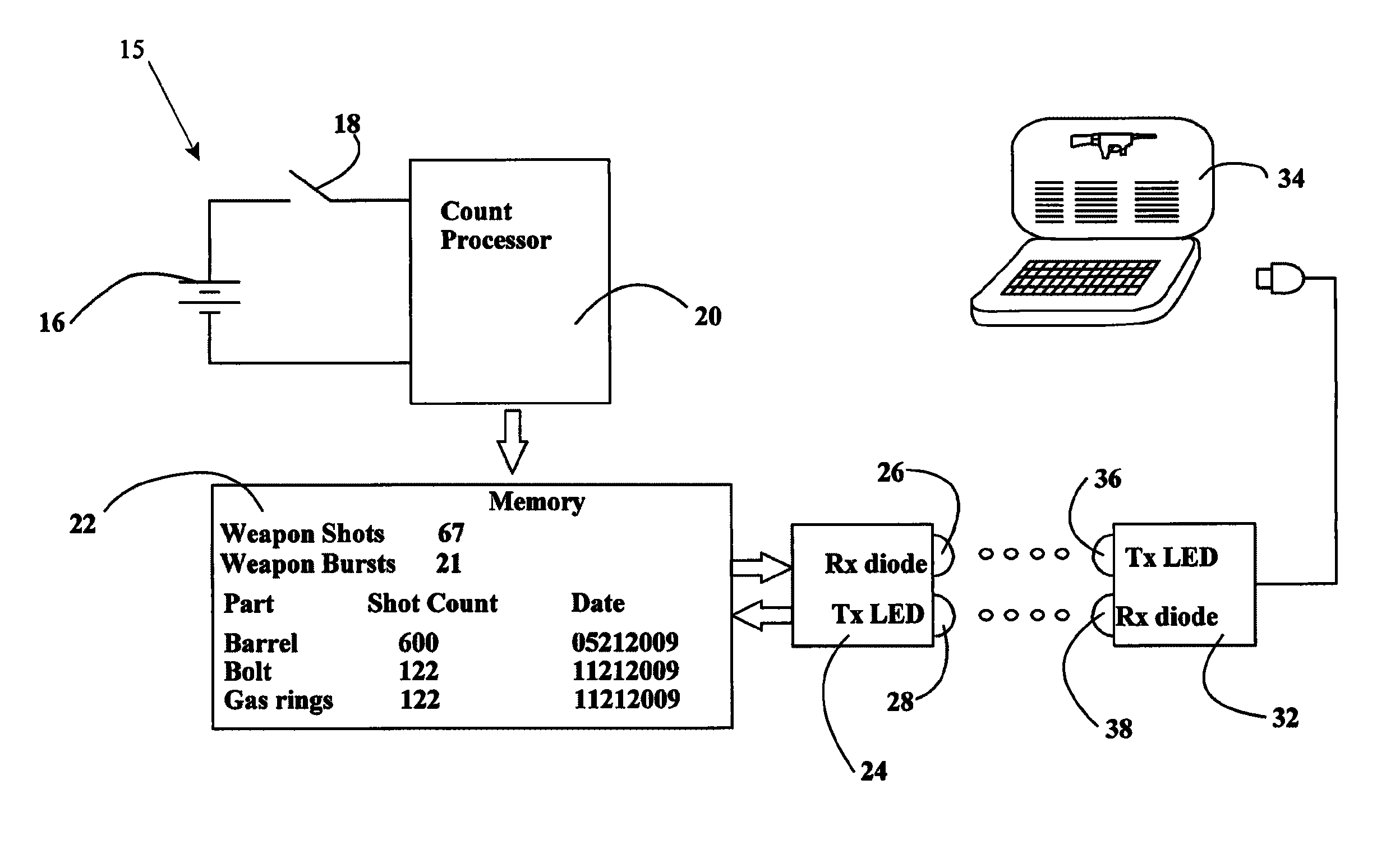
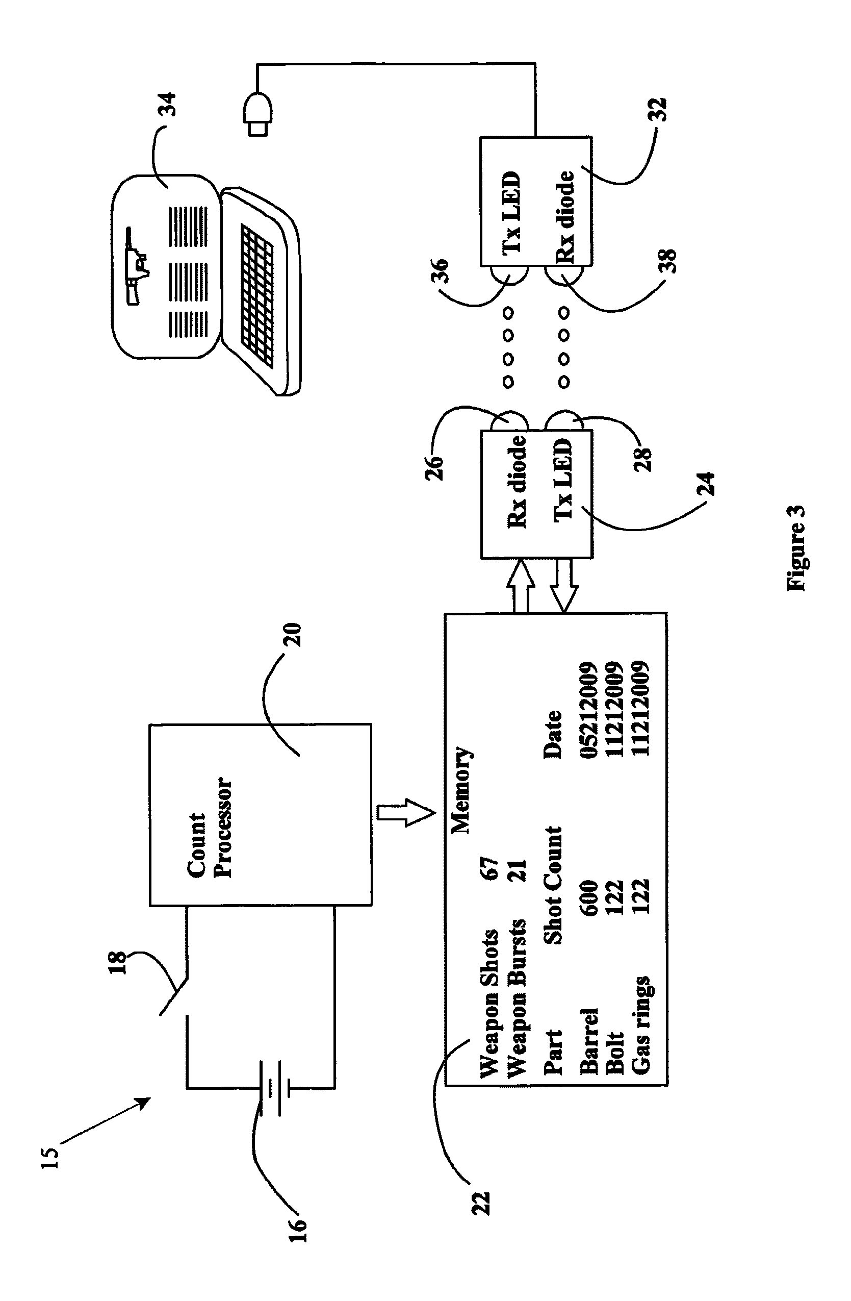
The significant drawback of the WEAR system is that the data for all weapons is stored in a central database; the firearm mounted shot counters are simple devices that count shots and communicate that count for analysis, and they do not contemplate or provide for data to be communicated into the shot counter device that is mounted on the weapon.
This creates the significant disadvantage that the WEAR system, to be effective, requires accessibility to the central database anytime and from anywhere to maintain the firearm.
It is also disadvantageous because data entry errors in the serial number or inputting of data invariably occur.
The constraints and challenges to providing a reliable shot counter, with a related system that allows for storage and analysis of data, including firearm maintenance data, are significant.

Method used


Image

  • Firearm maintenance system
  • Firearm maintenance system
  • Firearm maintenance system

Examples


Embodiment Construction

[0037]The present invention provides a usage based preventive maintenance system for firearms wherein all maintenance data is stored on the firearm itself in a durable and protected device so that succeeding analysis of the health of the firearm reflects the prior maintenance performed on the firearm as well as a running total of shots fired by the firearm. The present firearm maintenance system is advantageous because it allows individual components of a firearm to be analyzed and, if necessary, repaired or replaced, rather than overhauling the entire firearm, and it does so by accessing the shot count and maintenance history stored entirely on the firearm itself.

[0038]The most important element of the present system is the firearm mounted shot counter device 10. Shown for illustration purposes as a cylinder 10 encasing multiple components, the shot counter device 10 is typically mounted in the handle 12 of a weapon 14. The shape and mounting position on the firearm 14 of the shot ...


PUM


Abstract

A firearm maintenance system wherein a count for the number of times the firearm is fired is kept and stored in memory that is resident on the firearm. Also installed on the firearm are a shot counter device, including an inertia switch, a communication card, and an extended life battery. An epoxy resin encases the memory, shot counter device, communication card and battery to protect them from detrimental environmental effects. The life of various component parts of the weapon are tracked against the shot count of the weapon and replaced at appropriate intervals. Weapon maintenance is performed by transferring the weapon's data from the weapon's memory to an operator laptop computer wherein an algorithm analyzes the data and advises the operator to take necessary maintenance steps, such as replacing parts that have reached the end of their useful life. After performing such necessary maintenance, the operator makes a maintenance data submission that updates the memory to reflect the maintenance data steps taken. Data is transferred between the weapon and laptop computer via infrared communication such that no electrical connection to the weapon mounted device is necessary to communicate data into or out of the device.

Description

FIELD OF THE INVENTION[0001]The present invention relates generally to a system for maintaining firearms, and is particularly directed to a system wherein a shot counter device is mounted on a firearm and accumulates and retains data about the maintenance status of the firearm that is transmitted and analyzed by a computer.BACKGROUND OF THE INVENTION[0002]Effective maintenance of a firearm begins with an effective and regularly scheduled way to schedule and perform routine maintenance on the firearm. In the past, maintenance was performed when an individual component failed, or began to fail. At that point, the firearm would generally be rebuilt, repairing or replacing all components of the firearm subjected to wear and tear during usage.[0003]In recent years, preventive maintenance systems have been used to anticipate failure of the firearm, or of individual components, and to implement maintenance procedures to repair or replace components of the firearm before they fail. Such pre...

Claims


Application Information

Patent Timeline
Patent Type & Authority Patents(United States)
IPC IPC(8): F41A9/62
CPCF41A19/01
Inventor HARPER, JOHN
Owner HARPER JOHN
Why Eureka
Try Eureka