Hold and drive tool with disengagement capability

a technology of disengagement capability and tool, which is applied in the direction of screwdrivers, metal-working devices, wrenches, etc., can solve the problems of premature failure of tools, and the durability of the hold member, so as to reduce tool maintenance costs and downtime.

Inactive Publication Date: 2013-06-18
GM GLOBAL TECH OPERATIONS LLC
View PDF12 Cites 3 Cited by
  • Summary
  • Abstract
  • Description
  • Claims
  • Application Information

AI Technical Summary

Benefits of technology

[0005]An advantage of an embodiment is that the clutch control of the hold member reduces tool maintenance costs and down time when this tool is used to fasten components together.

Problems solved by technology

An issue with these types of tools is the durability of the hold member that prevents the fastener from rotating.
This may lead to premature failure of the tool, which results in the tool having to come off-line to change the hold member (or a portion thereof).
This reduces the time the tool is available for use and adds to the cost of assembling the components being fastened together.

Method used


Image

  • Hold and drive tool with disengagement capability
  • Hold and drive tool with disengagement capability
  • Hold and drive tool with disengagement capability

Examples


Embodiment Construction

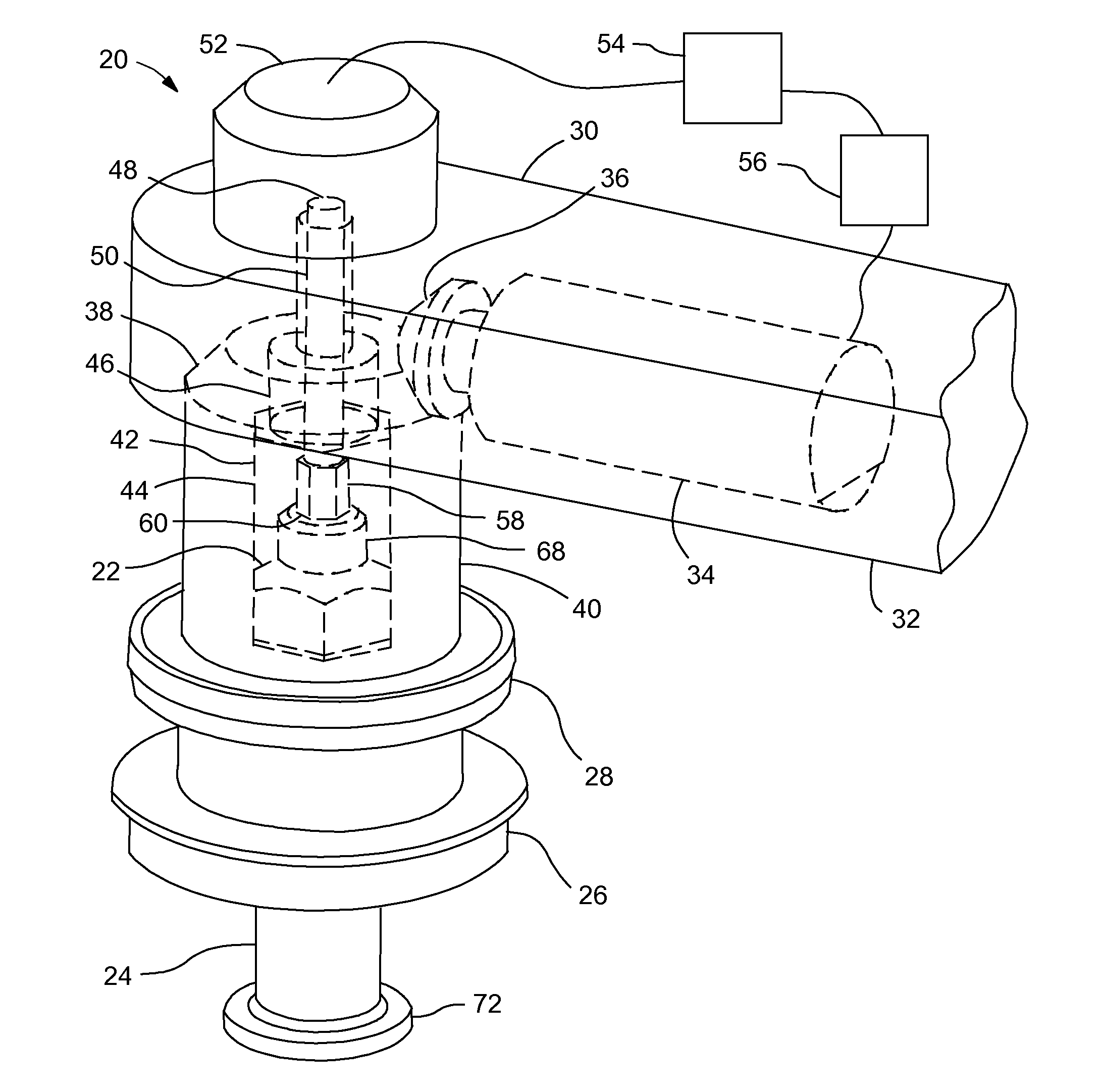
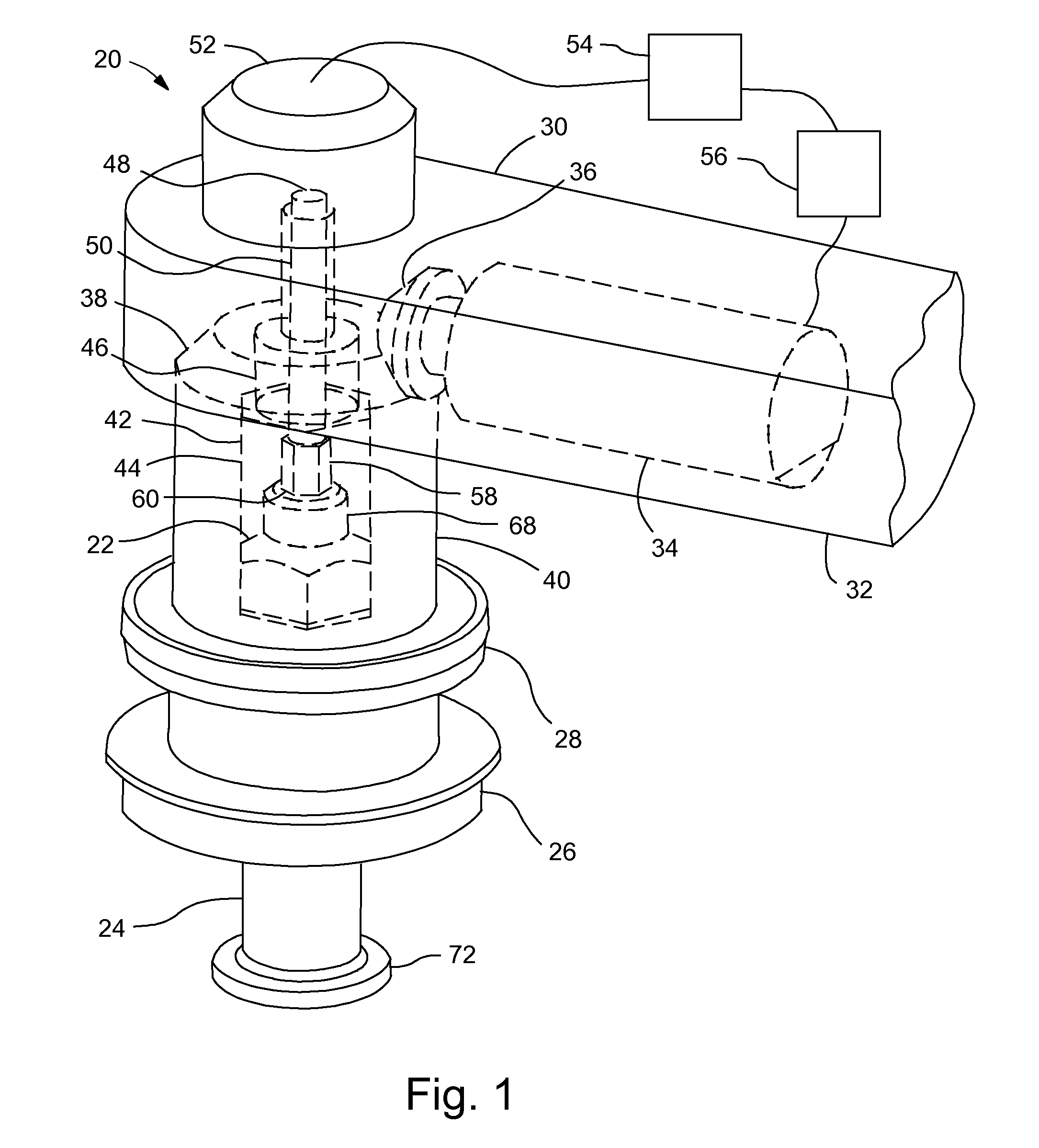
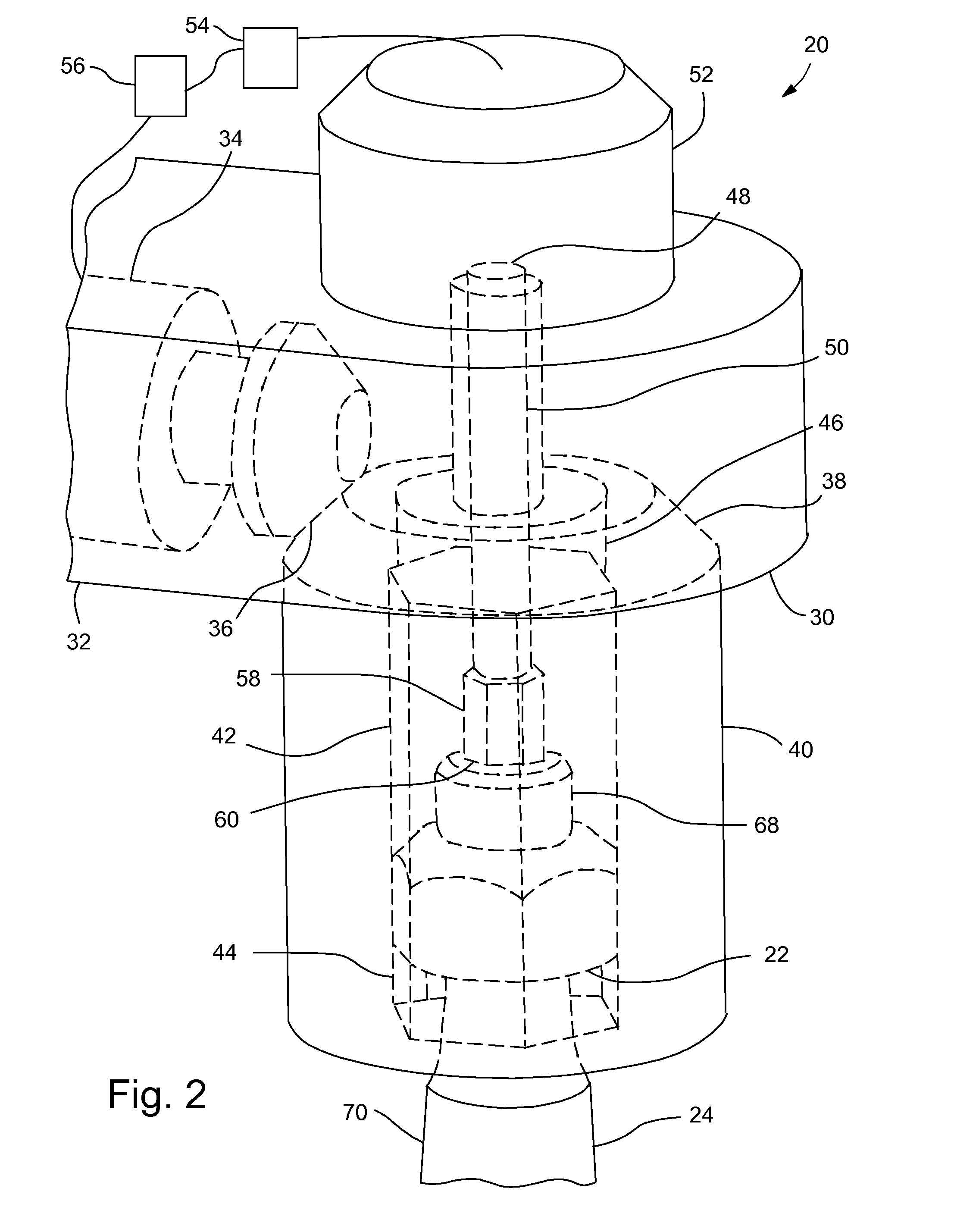
[0010]FIGS. 1-4 illustrate various portions of a hold and drive tool 20 engaging a nut 22 on a stud 24, which are used to secure a first member 26 (shown in FIG. 1) to a second member 28 (shown in FIG. 1). The stud 24 may be a tapered stud.

[0011]The hold and drive tool 20 includes a tool body 30 that may have a handle portion 32. A cavity in the tool body 30 includes a drive tool gear member 34, which may be, for example, electrically driven or pneumatically driven. The gear member 34 may include a bevel gear 36 that meshes with a mating bevel gear 38 on a nut drive member 40.

[0012]The nut drive member 40 includes a central bore 42 having a nut engaging portion 44 that is shaped to engage and rotate the nut 22. For example, this portion may be hexagonal if the nuts 22 to be driven are typical hexagonal nuts. Another portion 46 of the central bore 42 opens into a recess in the tool body 30 and allows for a hold member 48 to extend therethrough.

[0013]The hold member 48 has a hold shaf...


PUM

PropertyMeasurementUnit
torqueaaaaaaaaaa
shapeaaaaaaaaaa
electrically drivenaaaaaaaaaa

Abstract

A hold and drive tool and method of operation for fastening parts together with a stud and nut. The tool may comprise a tool body including a drive member therein, with the drive member rotationally driven by a power source; a nut drive member engaging the drive member and including a nut engaging portion received on the nut and rotating the nut relative to the stud; a hold member including a hold shaft connected to a hold bit, with the hold bit located in the nut drive member and received on a hold feature on the stud to prevent the stud from rotating relative to the hold member; and a clutch secured to the tool body and the hold shaft, with the clutch selectively allowing for and preventing rotation of the hold shaft relative to the tool body.

Description

BACKGROUND OF INVENTION[0001]The present invention relates generally to tools for driving nuts onto a fasteners and more particularly to such tools that hold the fastener while driving the nut.[0002]Some tools used to secure a nut to a fastener are designed to engage the fastener to prevent it from spinning as the nut is driven onto the fastener. Such tools are sometimes employed, for example, in the assembly of automotive vehicles. An issue with these types of tools is the durability of the hold member that prevents the fastener from rotating. At the end of the assembly operation putting the nut onto the fastener, the torque used to create the joint may transfer into the hold member. This may lead to premature failure of the tool, which results in the tool having to come off-line to change the hold member (or a portion thereof). This reduces the time the tool is available for use and adds to the cost of assembling the components being fastened together.SUMMARY OF INVENTION[0003]An ...

Claims


Application Information

Patent Timeline
Patent Type & Authority Patents(United States)
IPC IPC(8): B25B23/14B23P11/00
CPCB25B21/002Y10T29/49948
Inventor ZALOGA, MIROSLAWDENT, JONATHAN L.
Owner GM GLOBAL TECH OPERATIONS LLC
Why Eureka
Try Eureka