Method and machine for the production of reinforcement and dowel side frames for concrete reinforcement from wire or rod or other material of prismatic cross section

a technology of prismatic cross section and machine, which is applied in the direction of domestic products, applications, domestic applications, etc., can solve the problems of high production cost, difficult to maintain the proper product geometry, and not very consistent welding quality, so as to achieve faster and simpler production of higher-quality products, high quality

Active Publication Date: 2009-10-27
ANAGNOSTOPOULOS ANTONIOS
View PDF9 Cites 2 Cited by
  • Summary
  • Abstract
  • Description
  • Claims
  • Application Information

AI Technical Summary

Benefits of technology

[0008]Accordingly, it is an object of the present invention to present a method, which will overcome all the disadvantages of the existing methods and machines and which will lead to the manufacture of a machine, that will allow the fully automated manufacturing of the product, at a consistently high quality, and with flexibility in the manufacturing of a variety of products, i.e. leading to faster and simpler production of higher-quality products.
[0009]It is a further object of this invention to supply a machine, which automates the production of frames for concrete reinforcement, maximizes the machine flexibility and minimizes time for the machine adjustments (down time), produces excellent-quality product, where at the same time, it maintains simple design, reliable operation, user friendliness and high product capacity.
[0011]It is yet a further object of the present invention to provide a method and machine for the production of the transversal frames with the aid of a forming mold and forming tools that may be quickly and simply changed. Also according to the machine and method, the welding of the formed transversal wire with at least one of the two longitudinal wires at the formation location may be effected without the need for a mechanism for the transfer of the formed transversal wire from its formation location to some other location for welding. Accordingly, a high-quality final product may be obtained since the welding of the formed transversal wires may occur simultaneously with their formation, thus preserving their shape without allowing deformations due to elastic recuperation. Thus, the machine and method may also lend themselves to the production of a variety of shapes of transversal wire frames, which are welded to at least one longitudinal wire at the formation location. As a further advantage, the transversal wires need not be protruding from the second longitudinal wire. Furthermore, the product step may be easily changed since it only relates to the change of the length of the advancement of the wires and the location of the welding devices. In summary, the invention provides a simple implementation and simple procedures.

Problems solved by technology

The disadvantages of the semi-automated manufacturing mode are the difficulty in maintaining the proper product geometry, the not-very consistent welding quality, and the high production cost.
The transfer mechanism of the already formed transversal frame constitutes the main disadvantage of the automated production methods, since the transfer mechanism makes the overall machine operation very complicated and expensive.
Furthermore, the wire undergoes elastic deformation (recuperation), resulting in changes in the final product geometry and various inaccuracies during the transverse frame transfer.

Method used


Image

  • Method and machine for the production of reinforcement and dowel side frames for concrete reinforcement from wire or rod or other material of prismatic cross section
  • Method and machine for the production of reinforcement and dowel side frames for concrete reinforcement from wire or rod or other material of prismatic cross section
  • Method and machine for the production of reinforcement and dowel side frames for concrete reinforcement from wire or rod or other material of prismatic cross section

Examples


Embodiment Construction

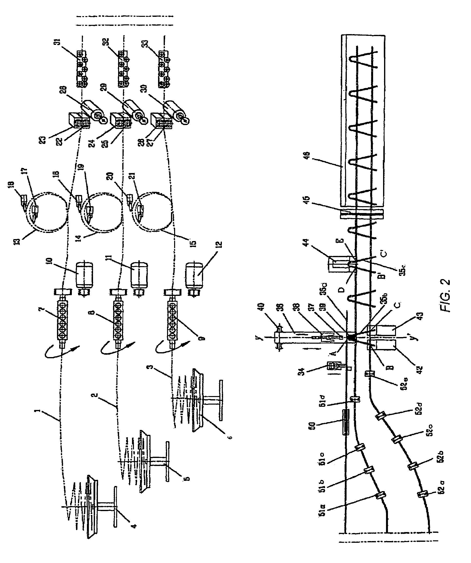
[0040]As depicted beginning in FIG. 2, three pay-off stations (4), (5) and (6) feed the wires (1), (2) and (3) into the machine. To explain terminology used throughout the remainder of the detailed description and appended claims, the following definition of terms is clarified: For simplicity and ease of reference thereto, the terms “wire,”“wire rods,”“rods,”“tubes,” and “material of prismatic cross-section” are used interchangeably and equivalently throughout the remainder of the detailed description and appended claims. Thus artisans in the art will readily understand that the term “rods” within the appended claims encompasses and includes the aforesaid “wire,”“tubes,” and generally “material of prismatic cross-section” without differentiation unless such differentiation is explicitly set forth. Any utilizable materials of prismatic cross-section may be conveniently and clearly referred to in non-limiting, simplified brief form by the terms “rods,” or “wires.” The three wires are ...


PUM

PropertyMeasurementUnit
lengthaaaaaaaaaa
lengthsaaaaaaaaaa
flexibilityaaaaaaaaaa

Abstract

According to the method, the transversal wire or rebar to be formed (1) and the longitudinal wires or rebars or other material of prismatic cross section (2), (3) are fed to the main forming and welding machine subsystem, in a stepwise manner, at the appropriate distance each time, through a driving mechanism (22-30). At this location, the transversal wire (1) is cut and then formed upon the action of a press (36). Welding of the formed transversal frame with one of the two longitudinal wires is performed while the formed transversal wire is still restrained by the action of the press (38) at the formation location. Welding with the second longitudinal wire is performed at the next production step, simultaneously with the welding of the next transversal frame with the first longitudinal wire, at the formation location. After the welding action, the transversal frame is released by the press and the forming tools (37-39), and the next production step is initiated. The product is made in a continuous shape and is cut at the proper lengths, by a cutter (45).

Description

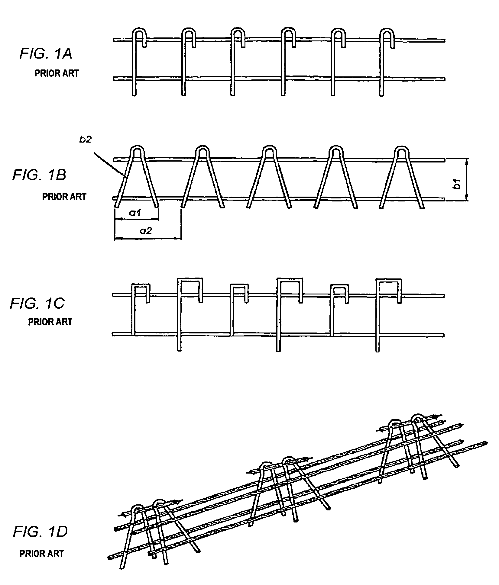
[0001]This application is a 371 national-phase entry of PCT Intenational application No. PCT / GR01 / 00050 filed on Dec. 27, 2001, the entirety of which is incorporated herein by reference for all intents and purposes as if fully set forth herein, and which claims foreign priority benefit of Greek national application No. 20010100096 filed on Feb. 22, 2001.BACKGROUND OF THE INVENTION [0002]The present invention refers to a method and a machine for the production of reinforcement and Dowel side frames for concrete, from wire or rod or other material of prismatic cross section.[0003]In order to assist in understanding the field of the invention, several representative products that may be delivered by the machine, according to the present invention, are presented in FIGS. 1A-1D. As shown there, the products are characterized by two parallel wire rods and by appropriately formed wire frames, which are welded transversely on specific points on the two parallel wires, in order to create a u...

Claims


Application Information

Patent Timeline
Patent Type & Authority Patents(United States)
IPC IPC(8): B23P11/00B21D47/00B21F27/20
CPCB21F27/20Y10T29/49627Y10T29/49813Y10T29/4998Y10T29/5121Y10T29/49798Y10T29/49968
Inventor ANAGNOSTOPOULOS, ANTONIOS
Owner ANAGNOSTOPOULOS ANTONIOS
Why Eureka
Try Eureka