
Adjustable fastening device and method for producing a prefabricated subassembly from at least one adjustable fastening device and a component

a technology of adjustable fastening and prefabricated components, which is applied in the direction of threaded fasteners, fastening means, sheet joining, etc., can solve the problems of drum screw supply and mounting individually, time-consuming and cost-intensive work steps, etc., and achieves the effect of simple and fast production

Inactive Publication Date: 2016-12-29
SCHMIDT HEIKO
View PDF4 Cites 3 Cited by
  • Summary
  • Abstract
  • Description
  • Claims
  • Application Information

AI Technical Summary

Benefits of technology

The invention is an adjustable fastening device and method for producing prefabricated subassemblies. The device includes a sleeve nut with a rivet collar and central sleeve portion that accommodates the tension screw lead-through of the drunk screw. The design ensures stable screw connection and pre-mounting of the adjustable fastening device. The central sleeve portion tapers conically to allow for fast and reliable connection between the drunk screw and sleeve nut while increasing the screw-in depth. The thread of the tensioning screw engages with the internal thread of the sleeve nut without any problem. The invention solves the problems of previous designs and makes the production process simpler and faster.

Problems solved by technology

However, it is a disadvantage that welding the sleeve nut to the plate-shaped component is required, which represents an additional time-consuming and cost-intensive work step within the production of prefabricated subassemblies.
Also, the drum can be inserted into the sleeve nut only after the welding process, i.e., when mounting the prefabricated subassembly in the course of the series production, there is the disadvantage that the drum screw needs to be supplied and mounted individually.

Method used


Image

  • Adjustable fastening device and method for producing a prefabricated subassembly from at least one adjustable fastening device and a component
  • Adjustable fastening device and method for producing a prefabricated subassembly from at least one adjustable fastening device and a component
  • Adjustable fastening device and method for producing a prefabricated subassembly from at least one adjustable fastening device and a component

Examples


Embodiment Construction

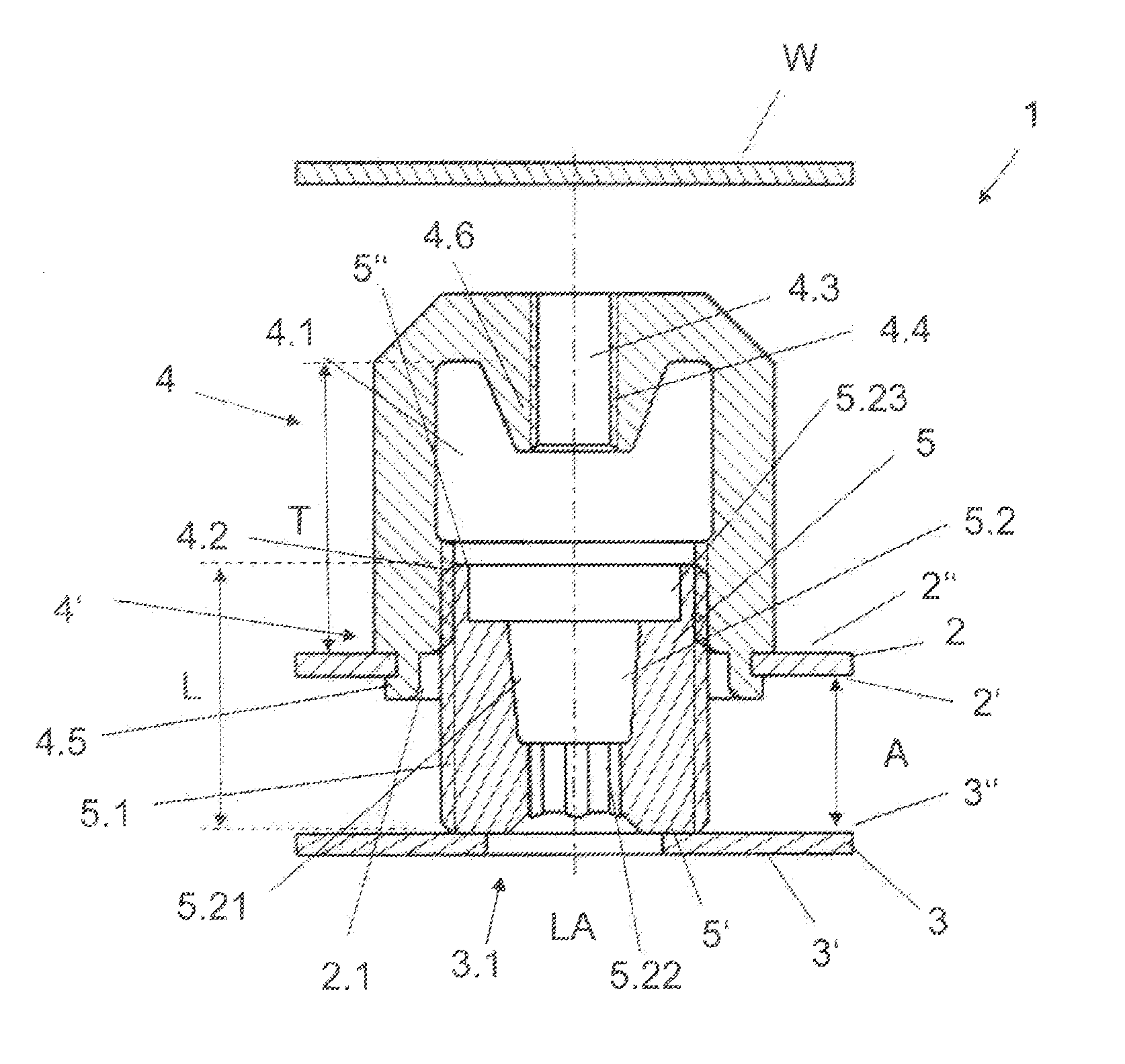
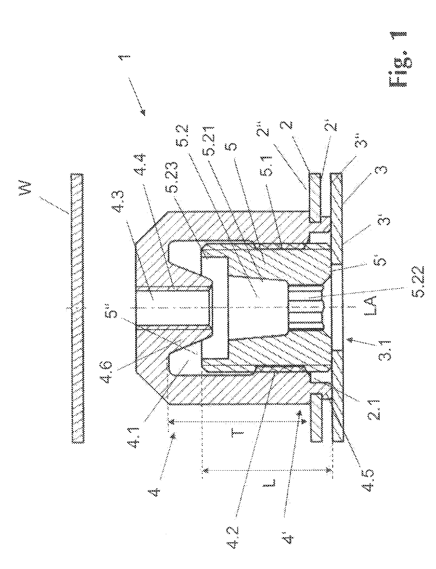
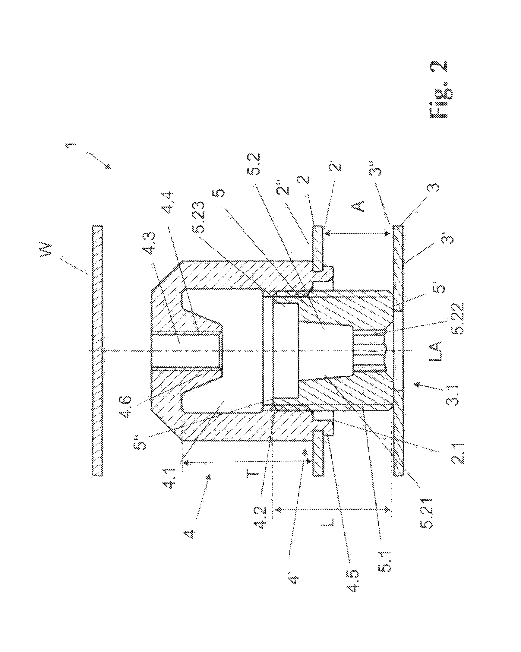
[0020]In the FIGS. 1 to 4, an adjustable fastening device designed according to the invention which is non-rotatably connected to a first component 2 which is flat at least in certain sections is in each case designated by 1. The adjustable fastening device 1 is provided for establishing a connection between the first component 2, which is flat at least in certain sections, and a second component 3, which likewise is flat at least in certain sections, at a specified distance A. FIGS. 1 to 4 show in each case a schematic longitudinal section through the adjustable fastening device 1 in different section planes which run parallel to one another and which run in or parallel to the longitudinal axis LA of the adjustable fastening device 1.

[0021]Both the first component 2 and the second component 3 are preferably made of a flat material from metal or plastics, for example from sheet steel, and can be parts of a holder for a housing wall or a support frame of an appliance or a machine, in...


PUM


Abstract

The invention relates to an adjustable fastening device including at least one sleeve nut having an aperture with a first internal thread and a through-bore following the same along the longitudinal axis of the fastening device (1), and also including a drum screw with an external thread and a tensioning screw lead-through, in the case of which the drum screw engages, by way of the external thread, in the first internal thread of the sleeve nut. According to the invention, the sleeve nut has on the free peripheral region, which forms the opening of the aperture, a rivet-collar portion and a central sleeve portion, which projects into the aperture in the direction of the rivet-collar portion, wherein the tensioning-screw lead-through of the drum screw is designed to accommodate the central sleeve portion at least in part.

Description

BACKGROUND OF THE INVENTION[0001]The invention relates to an adjustable fastening device composed of at least one sleeve nut having an aperture with a first internal thread and a through-bore following the first internal thread along a longitudinal axis (LA) of the adjustable fastening device and to a method for producing a prefabricated subassembly comprising at least one first component made of a flat material from a metal or a plastic, and an adjustable fastening device comprising at least one sleeve nut having an aperture with a first internal thread and a through-bore following the first internal thread along the longitudinal axis (LA) of the adjustable fastening device, and comprising a drum screw with an external thread and a tensioning screw lead-through.[0002]Adjustable fastening devices for fastening at least one component made from flat material to another component, preferably a holding component, at a specified distance from one another are in principle known.[0003]The ...

Claims


Application Information

Patent Timeline
Patent Type & Authority Applications(United States)
IPC IPC(8): F16B5/02F16B37/06
CPCF16B37/065F16B5/0233
Inventor SCHMIDT, HEIKO
Owner SCHMIDT HEIKO
Learn More