Method for manufacturing an acoustic panel

a technology of honeycomb core and manufacturing method, which is applied in the field of honeycomb core manufacturing, can solve the problems that short fibres do not allow the manufacture of such textile preforms, and achieve the effect of cost, weight and thickness

Pending Publication Date: 2021-10-21
SAFRAN CERAMICS SA
View PDF7 Cites 2 Cited by
  • Summary
  • Abstract
  • Description
  • Claims
  • Application Information

AI Technical Summary

Benefits of technology

[0043]The resulting composite acoustic panel is preferably made of composite material comprising an oxide matrix and long oxide fibres in

Problems solved by technology

In contrast to long fibres, short fibres do not

Method used


Image

  • Method for manufacturing an acoustic panel
  • Method for manufacturing an acoustic panel

Examples


first embodiment

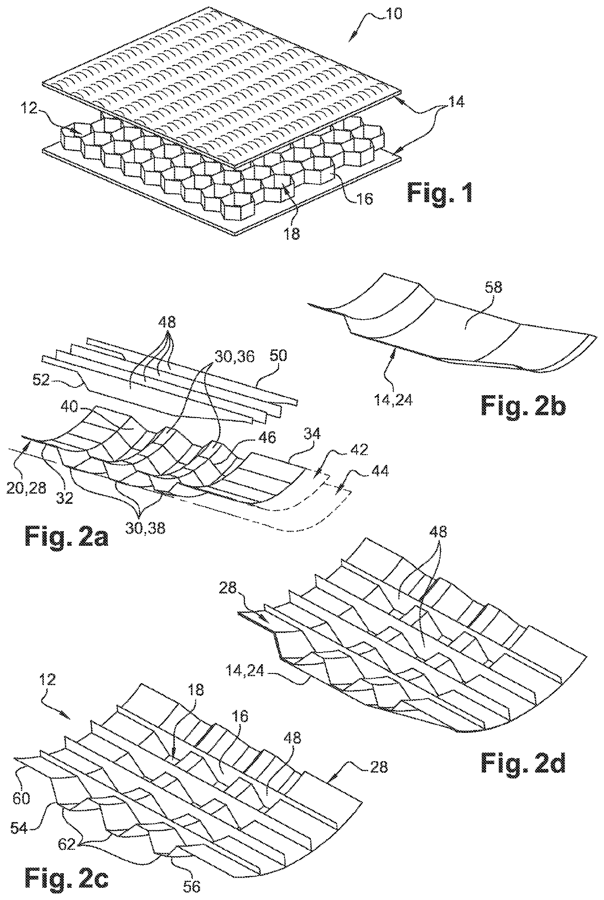
[0059]Reference is now made to FIGS. 2a to 2d, representing the process of obtaining an acoustic panel 10 in ceramic matrix composite material according to the

[0060]The first, second, third and fourth composite walls 20, 22, 24, 26 are obtained, respectively, from a biaxial fibre web or a unidirectional fibre web.

[0061]In the case of biaxial fibre webs, the web is coated with a slurry so that the slurry penetrates into the porosities of the web and thus forms a composite wall. The slurry is filled with alumina powder and a binder, the binder may be a thermoplastic or a fugitive thermoset or a preceramic oxide thermoset. The binder allows the coated biaxial fibre web to be stiffened following heat treatment. Following a coating, the biaxial fibre web is passed under a press or vacuum tarp to ensure the compaction and penetration of the slurry into the fibre web. If the binder used is a fugitive binder, then the coated sheet is loosened, in the form of a heat treatment, so that the bi...

second embodiment

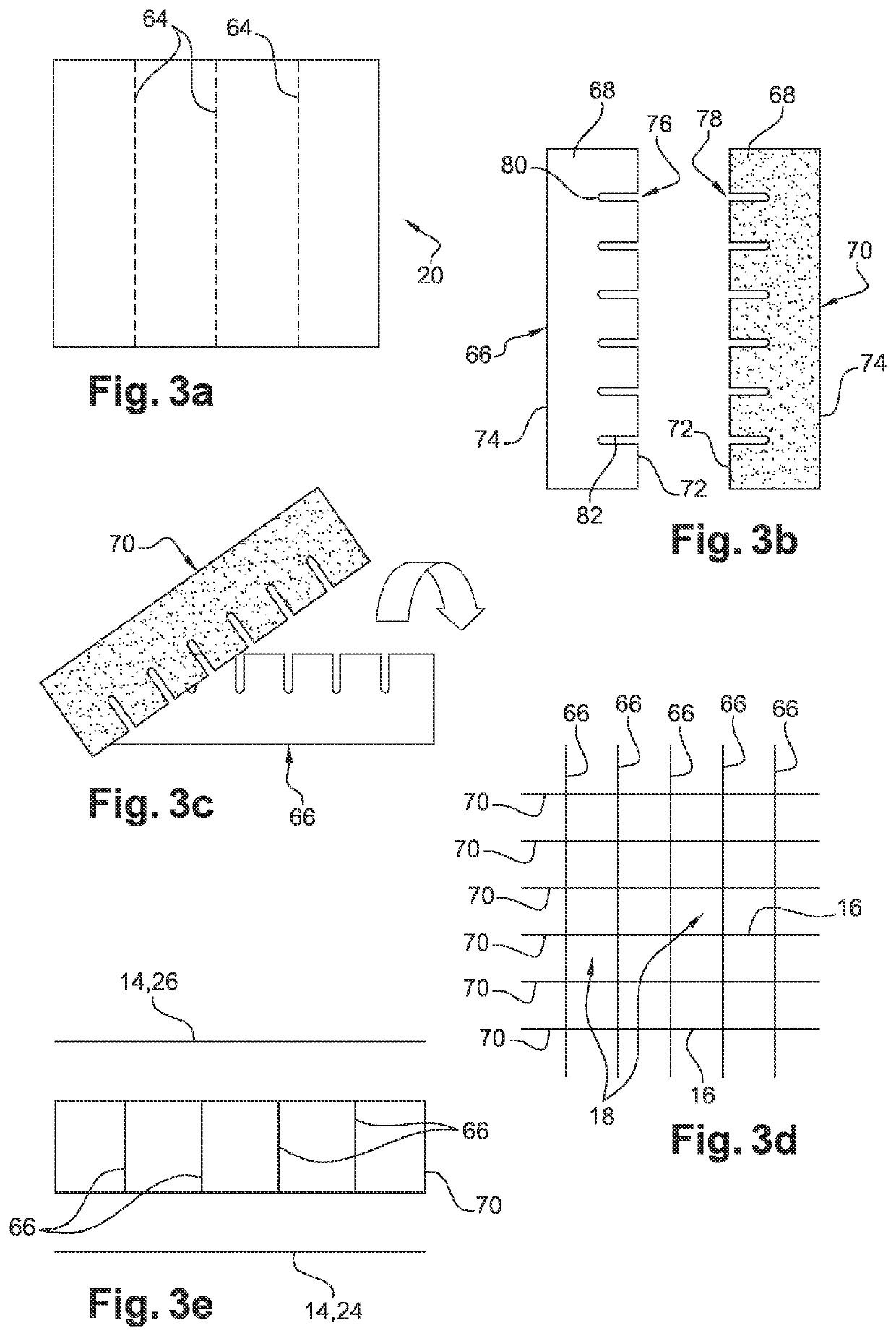
[0090]FIGS. 3a to 3e illustrate an acoustic panel according to the invention.

[0091]In the second embodiment of the composite acoustic panel 10, as in the first embodiment, the first, second, third and fourth composite walls 20, 22, 24, 26 are obtained respectively from a biaxial fibre fleece or a unidirectional fibre fleece.

[0092]FIG. 3a shows the first composite wall 20 obtained after coating and pressing or vacuum forming. Cut-out areas 64 of the first wall 20, in the form of parallel dashed lines, so as to form first strips 66, are illustrated. This cutting can be mechanical, by water jet, or laser. The first strips 66 have a roughly rectangular shape. The width 68 of each first strip 66 is of the order of 10 mm.

[0093]The second wall 22 is obtained by the same process as the first wall 20 and is also cut into second strips 70 having the same characteristics as the first strips 66.

[0094]Optionally, the first and second strips 66, 70 can be obtained from the first wall 20 and / or th...


PUM

PropertyMeasurementUnit
Widthaaaaaaaaaa
Areaaaaaaaaaaa

Abstract

A method for manufacturing a composite panel is described. The method includes producing a first wall, a second wall, a third wall and a fourth wall from composite materials including an oxide matrix and long oxide fibres; from the first and second walls, producing a cellular core including a plurality of cells, each cell including a first end and an opposing second end, covering the first and second ends of the cells of the cellular core with the third wall and the fourth wall, respectively, so as to close the ends of said cells.

Description

FIELD OF THE INVENTION[0001]The present invention concerns the field of panels, in particular those intended to equip the hot gas ejection zones of a turbomachine, and more precisely of an aircraft turbojet engine. The invention concerns more particularly a method of manufacturing a honeycomb core.BACKGROUND OF THE INVENTION[0002]Typically, a turbomachine has aerodynamic guide surfaces for the flow of the ejected hot gases, which can be subjected to high temperatures of up to 700° C. and in some cases up to 800° C.[0003]In order to reduce the noise emitted by the turbojet engine during operation, it is known to produce aerodynamic guide surfaces with acoustic panels 10 comprising a sandwich-type structure consisting of a honeycomb core 12 inserted between two covering walls, also called skins 14. The skins 14 of these panels 10 are made of metallic materials or ceramic matrix composites. The honeycomb core 12 is made of metallic, monolithic materials in the form of compacted powder ...

Claims


Application Information

Patent Timeline
IPC IPC(8): B32B37/14B32B5/02B32B3/12G10K11/168G10K11/172B32B7/12
CPCB32B37/146B32B5/02B32B3/12G10K11/168B32B2307/518B32B7/12B32B2307/102B32B2605/18G10K11/172B32B2315/02B64D33/06B32B18/00F02K1/822F05D2300/603F05D2250/283C04B2237/38C04B37/005C04B2237/062C04B2237/064C04B2237/06C04B2235/5264C04B2237/76B32B5/022C04B35/80C04B35/117C04B35/18C04B2235/483Y02T50/60B29C51/00B29C66/72525C04B35/01B29C66/7461B29C2045/1692
Inventor CLERAMBOURG, AURÉLIABOUILLON, ERICPHILIPPE, ERIC
Owner SAFRAN CERAMICS SA
Why Eureka
Try Eureka