Sheet manufacturing apparatus, sheet manufacturing system, control method of a sheet manufacturing apparatus, and sheet manufacturing method

a sheet manufacturing and control method technology, applied in the field of sheet manufacturing apparatus, sheet manufacturing system, sheet manufacturing method, can solve the problems of inability to replace parts, inability to inhibit thermal degradation of soft body, inability to easily flatten uneven surface of material, etc., to achieve the effect of improving the quality and texture of sheets produced, and not easily flattening uneven surfaces

Active Publication Date: 2021-05-18
SEIKO EPSON CORP
View PDF22 Cites 2 Cited by
  • Summary
  • Abstract
  • Description
  • Claims
  • Application Information

AI Technical Summary

Benefits of technology

[0010]The heater in this configuration is an integrated unit that is removably installable to the sheet manufacturing apparatus, and the heater unit can be installed and removed (replaced) as a single assembly to the sheet manufacturing apparatus. When the sheet manufacturing apparatus becomes unusable because the heater reached the end of its service life or a problem occurred, the heater (heater unit) that cannot be used can be replaced with a functioning heater (heater unit), and the sheet manufacturing apparatus can be quickly restoring to working condition.
[0048]By configuring the sheet manufacturing system with heaters suitable for making sheets of different quality and texture, the quality and texture of the sheets that are produced can be improved, and a wide variety of sheets can be made, by changing to the heater preferred for making sheets of different quality and texture. In addition, because the heater is removably installed to the sheet manufacturing apparatus, the down time of the sheet manufacturing apparatus required to exchange a heater is shorter than when the sheet manufacturing apparatus must be disassembled to replace the heater, and the efficiency (productivity) of the sheet manufacturing apparatus can be improved.Example 16

Problems solved by technology

In addition, because only the surface of the soft body is heated by the heater, thermal degradation of the soft body is inhibited compared with a configuration that heats the soft body throughout.
However, because the soft body of the sheet manufacturing apparatus described in JP-A-2016-130009 is heated, thermal degradation of the soft body is inevitable, and part replacement becomes necessary.
When part replacement becomes necessary due to thermal degradation of the soft body, the system must be shut down for a relatively long time to replace the part, and system efficiency (productivity) drops.
A configuration not having a soft body is conceivable, but when the material is held between the first roller and second roller in a configuration not having a soft body, unevenness in the material is flattened, producing glossiness in spots and making it difficult to produce sheets with a uniformly matte surface.
In addition, the service life of the heating and compression device (particularly the heater) is shortened, and when parts replacement or other maintenance become necessary, the system must be shut down for a relatively long time to replace the part, and system efficiency (productivity) drops.
If the heater is not configured as a unit, and the sheet manufacturing apparatus is restored by disassembling the heater and replacing the unusable part, disassembling and reassembling the heater may take a long time, and the operation of the sheet manufacturing apparatus may stop for a long time.
This creates a loss from being unable to produce sheets while changing the operating parameters of the heater.
If a new heater is acquired after the heater reaches its service life, and a spare heater is not in stock, acquiring a new heater may take a long time, and the time the apparatus is stopped to install a new heater may be long.
However, if the service life of the heater is predicted and a new heater is made ready before the heater reaches the end of its service life, even if a spare new heater is not kept in stock, a new heater can be readied before the heater reaches the end of its service life, and the length of time the apparatus is stopped to install a new heater can be shortened.

Method used


Image

  • Sheet manufacturing apparatus, sheet manufacturing system, control method of a sheet manufacturing apparatus, and sheet manufacturing method
  • Sheet manufacturing apparatus, sheet manufacturing system, control method of a sheet manufacturing apparatus, and sheet manufacturing method
  • Sheet manufacturing apparatus, sheet manufacturing system, control method of a sheet manufacturing apparatus, and sheet manufacturing method

Examples


embodiment 1

Outline of a Sheet Manufacturing Apparatus

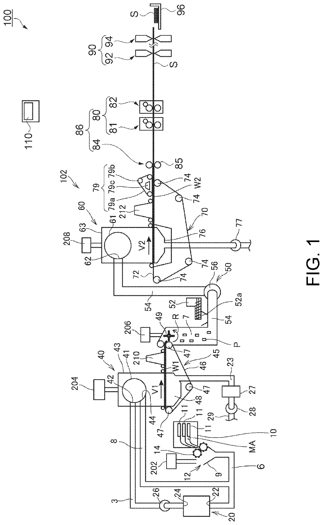
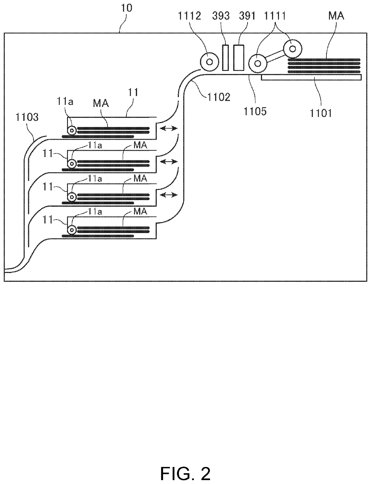
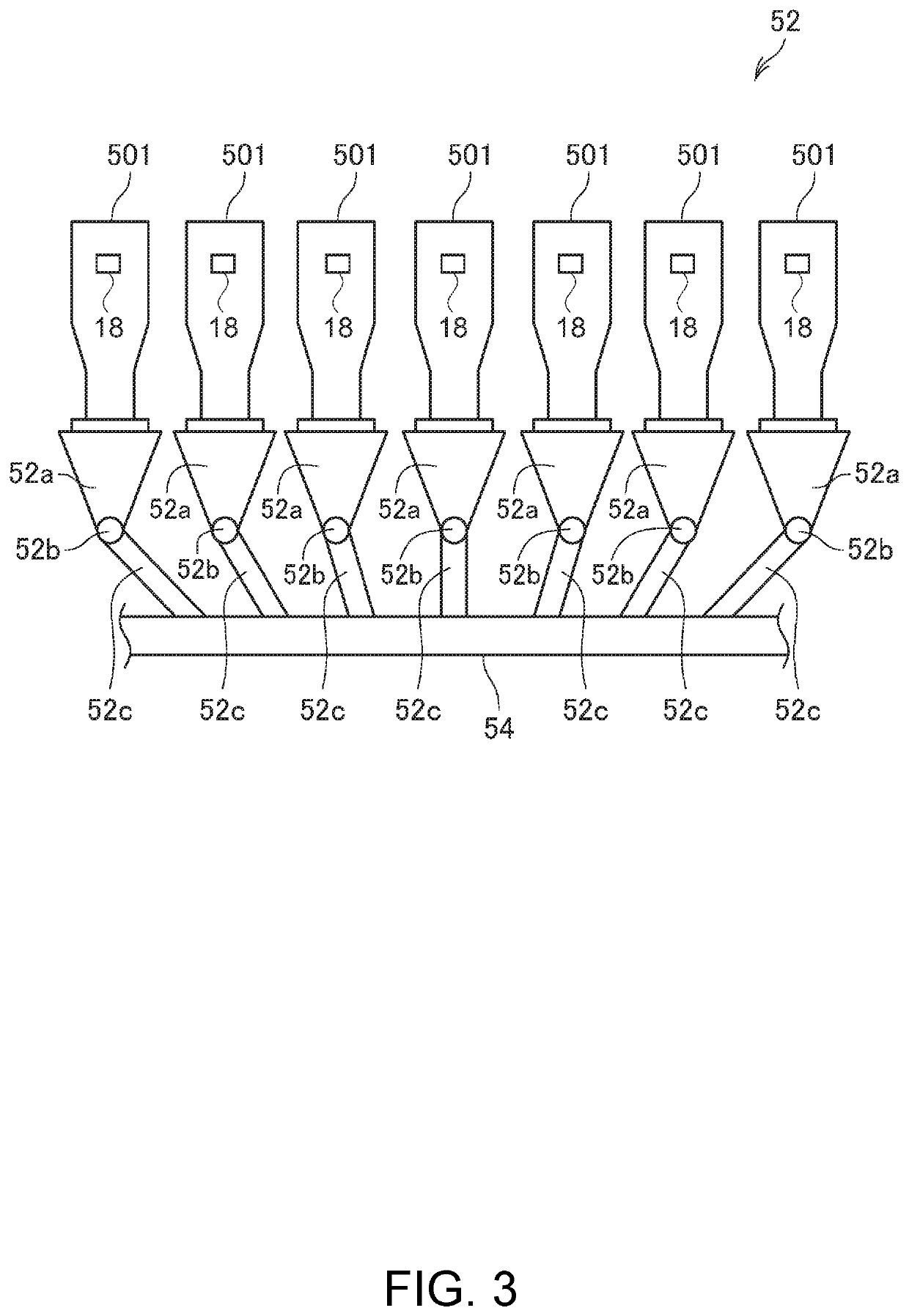
[0081]FIG. 1 schematically illustrates the configuration of a sheet manufacturing apparatus according to a first embodiment of the invention. FIG. 2 illustrates the configuration of the supply device. FIG. 3 illustrates the conventional of the additive supplier.

[0082]A sheet manufacturing apparatus 100 according to this embodiment of the invention is described first with reference to FIG. 1 to FIG. 3.

[0083]The sheet manufacturing apparatus 100 according to this embodiment is convenient for defibrating feedstock MA such as confidential documents and other recovered paper in a dry process into loose fibers, and then producing new paper (sheet S) by through compression, heating, and cutting operations. By mixing various additives with the defibrated feedstock MA, the strength and whiteness of the paper product can be improved according to the application, and other desirable properties such as color, scent, and flame retardancy can be imparted....

embodiment 2

[0275]FIG. 11 illustrates the configuration of a sheet manufacturing apparatus according to the second embodiment of the invention. In FIG. 11 the sheet forming unit 86A is indicated by the dot-dash line.

[0276]This embodiment and the first embodiment described above differ in the configuration of the sheet forming unit, and are otherwise the same. More specifically, the sheet forming unit 86A in this embodiment comprises a compression device 84, two heaters 81 and 82, and two flappers 88, 89 that switch between paths 1 and 2. The sheet forming unit 86 in the first embodiment described above has a compression device 84 and two heaters 81 and 82, but does not have flappers that switch the conveyance path. This is the main difference between this embodiment and the first embodiment.

[0277]A sheet manufacturing apparatus 100A according to this embodiment is described next with reference to FIG. 11 and focusing on the differences with the first embodiment. Note that like parts in this and...

embodiment 3

[0289]FIG. 12 illustrates the configuration of a sheet manufacturing apparatus according to the third embodiment of the invention. In FIG. 12 the sheet forming unit 86B is indicated by the dot-dash line.

[0290]This embodiment and the first embodiment described above differ in the configuration of the sheet forming unit, and are otherwise the same. More specifically, the sheet forming unit 86B in this embodiment comprises a compression device 84, two heater groups 80A, 80B, and two flappers 88, 89 that switch between paths 1 and 2. The sheet forming unit 86 in the first embodiment described above has a compression device 84 and one heater group 80, but does not have flappers that switch the conveyance path. This is the main difference between this embodiment and the first embodiment.

[0291]A sheet manufacturing apparatus 100B according to this embodiment is described next with reference to FIG. 12 and focusing on the differences with the first embodiment. Note that like parts in this a...


PUM

PropertyMeasurementUnit
timeaaaaaaaaaa
operating temperatureaaaaaaaaaa
temperatureaaaaaaaaaa

Abstract

Provided is technology improving the efficiency (productivity) of a sheet manufacturing apparatus. A sheet manufacturing apparatus 100 manufactures sheets S by heating with heaters 81 and 82 a mixture (second web W2) of resin and fiber produced by defibrating feedstock MA. The heaters 81 and 82 each have a first roller 171, a second roller 172 that holds the second web W2 with the first roller 171, and a moving mechanism 190. The moving mechanism 190 can switch the first roller 171 and second roller 172 to a position holding the second web W2, and a first roller 171 and second roller 172 are separated and do not hold the second web W2. The heaters 81 and 82 are configured as units that can removably installed to the sheet manufacturing apparatus 100.

Description

BACKGROUND1. Technical Field[0001]The present invention relates to a sheet manufacturing apparatus useful for manufacturing paper (sheets), a sheet manufacturing system having the sheet manufacturing apparatus, control method of the sheet manufacturing apparatus, and a sheet manufacturing method.2. Related Art[0002]JP-A-2016-130009 and JP-A-2015-161035 describe dry process sheet manufacturing apparatuses having a forming unit that forms sheets by applying heat and pressure to material containing fiber and resin (binder), and produces paper (sheets) using extremely small amounts of water.[0003]For example, the sheet manufacturing apparatus described in JP-A-2016-130009 holds the material between a first roller and a second roller, and compresses and heats the material to make a sheet. The first roller has a core that is located in the center of the roller and coated with a soft body (rubber), and the outside (surface) of the soft body is heated by a heater. The second roller has a co...

Claims


Application Information

Patent Timeline
Patent Type & Authority Patents(United States)
IPC IPC(8): D21F7/00D21F9/04D21H21/06D21F11/06B27N3/00D21F5/00D21F9/00D04H1/60
CPCD21F9/046B27N3/00D04H1/60D21F5/00D21F7/00D21F9/00D21F11/06D21H21/06D21B1/06
Inventor YODA, KANEONAGAI, YOSHIYUKIOGUCHI, YUKIFUJITA, SHIGEOARAI, AKIRAICHIKAWA, KAZUHIROOGUCHI, TERUAKITANIGUCHI, SEIICHI
Owner SEIKO EPSON CORP
Why Eureka
Try Eureka