High performance kratky assembly

a high-performance, assembly technology, applied in the direction of instruments, material analysis using wave/particle radiation, diaphragm/collimeter handling, etc., can solve the problems of difficult to guarantee the high degree of stability required for ultra-low qmin applications, material annealing and aging are laborious, and may not easily meet the requirements of ultra-low qmin applications. the effect of low qmin

Active Publication Date: 2015-08-27
RIGAKU INNOVATIVE TECH
View PDF4 Cites 2 Cited by
  • Summary
  • Abstract
  • Description
  • Claims
  • Application Information

AI Technical Summary

Benefits of technology

[0008]The disclosed systems and methods provided improve performance of the Kratky blocks by addressing the two issues discussed above. Single crystal is a stress free material. Using a single crystal material will essentially eliminate the stress related stability problem. Interaction between x-rays and the single crystal material also yield much less parasitic scattering. Both in theory and practical experiments, it has been proved that the parasitic scattering can be reduced by three orders of magnitude by using single crystal material. Therefore, with the same degree of contamination to the Kratky blocks, the parasitic scattering from a single crystal block can be three orders of magnitude less than that from a steel alloy block, and the single crystal block will require much less maintenance and result in much less system down time.

Problems solved by technology

Still the problems may exist when used in certain applications.
First of all, material annealing and aging are tedious and may not easily guarantee the high degree of stability required by the ultra-low Qmin applications.
Secondly, X-rays interact with the Kratky blocks at the corners of each block and produce parasitic scattering.
However, any contamination on the surface of the block, which is out of the defined plane by the two blocks, would further scatter the parasitic scattering into the data collection zone, thus increase the Qmin.
Another minor issue in some camera designs is the alignment issues related to the resolution change.
However, for each change of the system resolution, one has to realign the beamstop which blocks the primary beam from entering the detector.

Method used


Image

  • High performance kratky assembly
  • High performance kratky assembly
  • High performance kratky assembly

Examples


Embodiment Construction

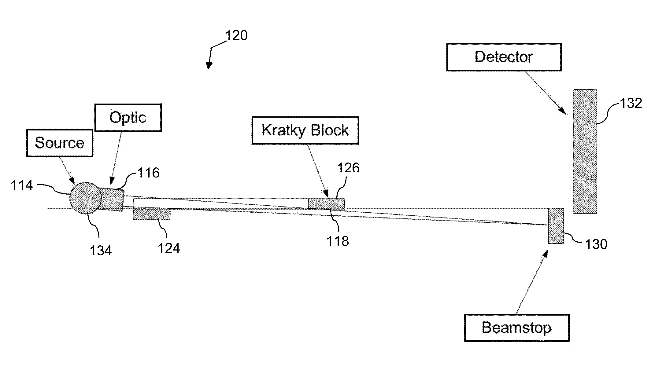
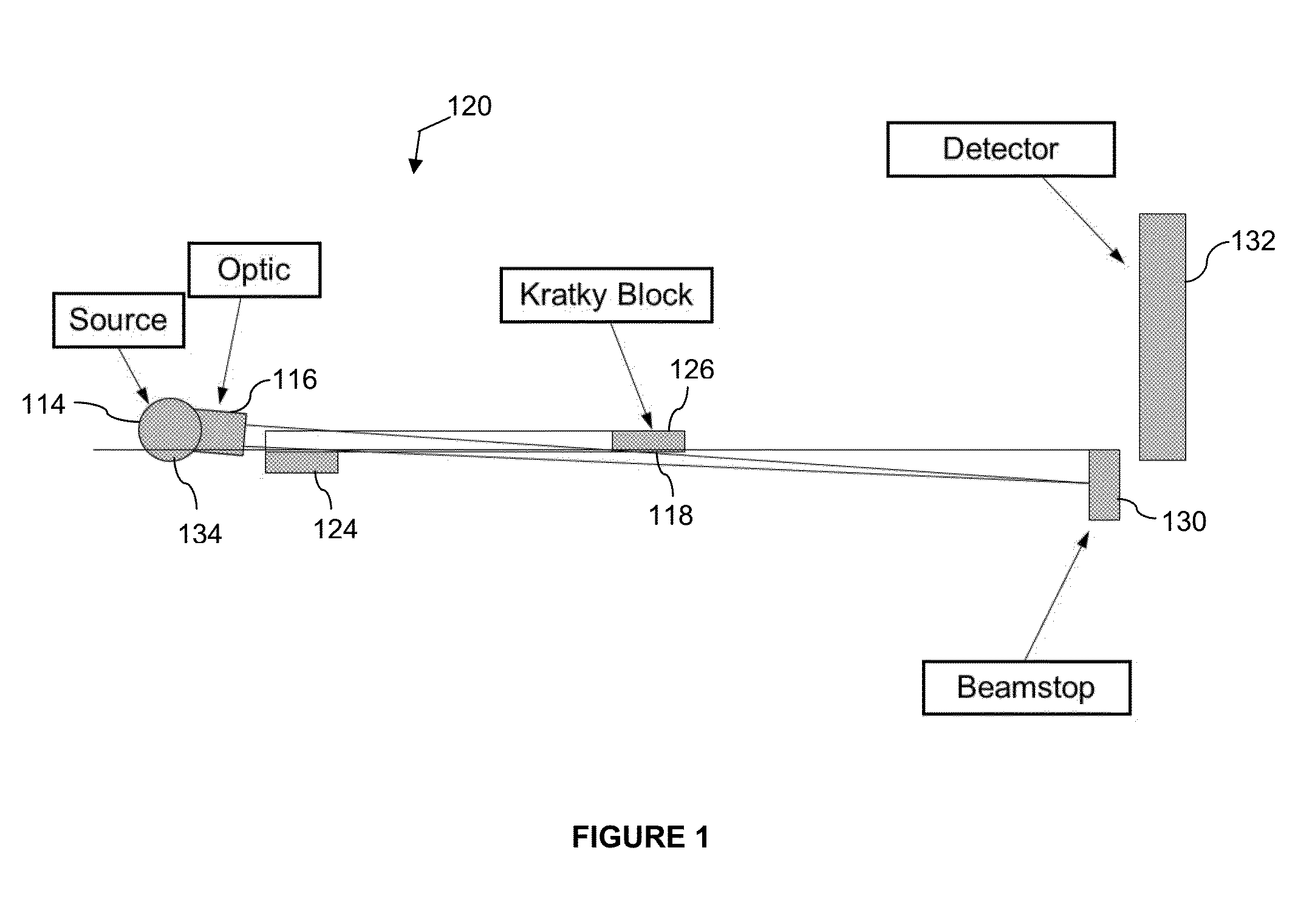
[0014]A system for improving a Kratky collimation assembly to provide a parasitic scattering free data collection zone is provided. The Kratky collimation assembly may be integrated within a SAXS Instrument. The Kratky collimation assembly may be made of single crystal or mosaic crystal. The single crystal or mosaic crystal may be stress free or with minimized stress. Using a single crystal or mosaic crystal simplifies the manufacturing process, reduces the need of annealing and provides long term stability. The single crystal material also produces much less parasitic scattering and is much less prone to the contamination which may further scatter the parasitic scattering into the data collection zone, thus reduces the need of maintenance. Further, a beamstop may be pre-fixed with the Kratky collimation assembly. In one exemplary implementation, the adjustment of the Kratky blocks will carry the beamstop so that the beamstop remains aligned with the Kratky blocks. The fixed relatio...


PUM

PropertyMeasurementUnit
widthaaaaaaaaaa
small angleaaaaaaaaaa
Small Angle X-aaaaaaaaaa

Abstract

An assembly for Kratky collimator is provided. The assembly may be used for a small angle x-ray camera or system requiring such filtering. The assembly may include a first block with a first working surface and a second block with a second working surface. The first and second blocks may be aligned with the first working surface pointing an opposite direction of the second working surface and the first working surface being aligned in a common plane with the second working surface. In some implementations, the first block may comprise a crystal material. In some implementations, an extension may of the first block may be configured position a beamstop.

Description

BACKGROUND[0001]1. Field of the Invention[0002]The invention relates to a Small Angle X-ray Scattering (SAXS) measurement system which uses Kratky assembly for beam conditioning.[0003]2. Description of the Known Art[0004]Kratky collimation has been used to create a parasitic scattering-free data collection space. Kratky collimation assemblies have been used by the traditional 1D Kratky camera and some newer 2D SAXS system (U.S. Pat. No. 7,734,011). The quality of the Kratky collimation assembly may be important to the performance of a small angle x-ray scattering (SAXS) camera to eliminate parasitic scattering. Specifically, the flatness of the working surfaces, alignment between the surfaces of the two blocks and the scattering characteristics of the Kratky blocks affect the background “cleanness” and the total flux on the sample for a given system resolution (Qmin). These qualities are elements that determine the highest resolution, the lowest Qmin, and the performance consistency...

Claims


Application Information

Patent Timeline
Patent Type & Authority Applications(United States)
IPC IPC(8): G01N23/201G21K1/04
CPCG01N23/201G21K2201/062G21K1/04G01N23/207G21K1/025G21K1/02
Inventor JIANG, LICAIPENNARTZ, PAUL ULRICH
Owner RIGAKU INNOVATIVE TECH
Why Eureka
Try Eureka