LED lamp and street lamp using the same

a technology of led lamps and street lamps, applied in outdoor lighting, semiconductor devices of light sources, lighting and heating apparatus, etc., can solve the problems of poor directivity of illumination, waste of electric energy, and defects of the above-mentioned implementation, and achieve excellent directivity of illumination, eliminate glare phenomenon, and uniform brightness

Inactive Publication Date: 2013-06-18
WANG ZHEN
View PDF3 Cites 0 Cited by
  • Summary
  • Abstract
  • Description
  • Claims
  • Application Information

AI Technical Summary

Benefits of technology

[0008]Accordingly, the present invention is directed to a novel LED lamp, which has excellent directivity of illumination, uniform brightness, can eliminate the glare phenomenon, and has desirable heat dissipation performance.
[0025]The LED lamp provided in the present invention has excellent directivity of illumination, uniform brightness, can eliminate the glare phenomenon, and has desirable heat dissipation performance. In addition, the LED lamp has various advantages of a simple structure, being conveniently mounted, energy-saving, environmental friendly, and so on.

Problems solved by technology

Unfortunately, the above two implementations still cannot overcome the defects of the conventional lighting lamps as follows.
Firstly, the directivity of the illumination is poor.
Secondly, the brightness is non-uniform, which results in a phenomenon of being bright at a close area and being dark at a distant area.
Due to the non-uniform distribution of the illumination, a light source with a higher power and a higher luminous flux has to be adopted in design, so as to enable dark areas at both sides of the road and between two lamps reach the lighting standard level, thereby meeting the luminance requirements of the dark areas, which results in wastes of electric energy.
Thirdly, the glare phenomenon cannot be eliminated.
The so-called glare phenomenon refers to that when people observe a certain visual object, a dazzling light-emitting spot existing in the visual field may affect the observing effect, which makes people feel uncomfortable.
Fourthly, the heat-dissipation problem is not well solved.
Currently, about more than 80% of the energy consumption of the LEDs is converted into heat energy, and the semiconductor elements are not high temperature resistant.
A lot of LEDs are concentrated in a relative small space, and the continuously increased heat makes the temperature of the LED chip become excessively high.
If the generated heat energy cannot be dissipated timely, the luminous efficiency and the service life of the LED may be severely decreased under a high temperature.
In most of the existing LED lamps, radiators are disposed horizontally, which have a poor heat convection effect.
The basic reasons for causing the above defects include that, the prior art cannot make full use of the directionality of LEDs, cannot effectively and reasonably control the light rays generated by the LEDs, and cannot effectively dissipate the heats for the LED lamps.

Method used


Image

  • LED lamp and street lamp using the same
  • LED lamp and street lamp using the same
  • LED lamp and street lamp using the same

Examples


first embodiment

[0036]Referring to FIGS. 2, 3, and 6, the LED lamp according to the present invention is further described below in detail.

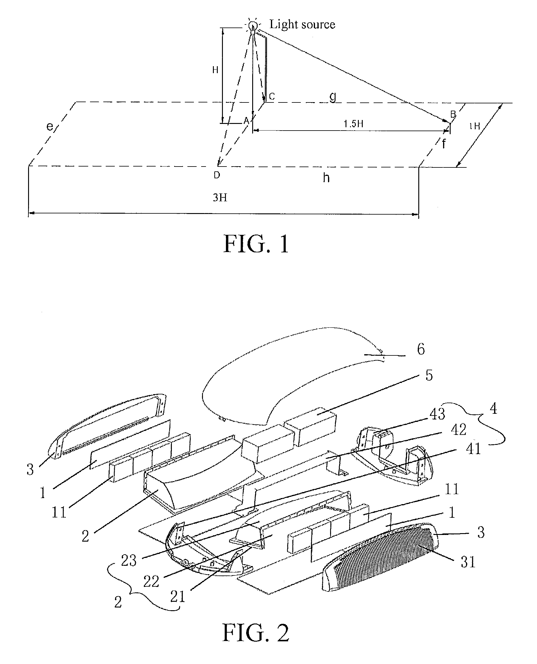
[0037]Referring to FIG. 2, the LED lamp of the present invention includes substrates 1, reflectors 2, radiators 3, a mounting frame 4, a power source 5, and a top cover 6. Each of the substrates 1 further includes a condenser cup 11, and the mounting frame 4 further includes a front caulking 41, a retaining plate 42, and a rear caulking 43.

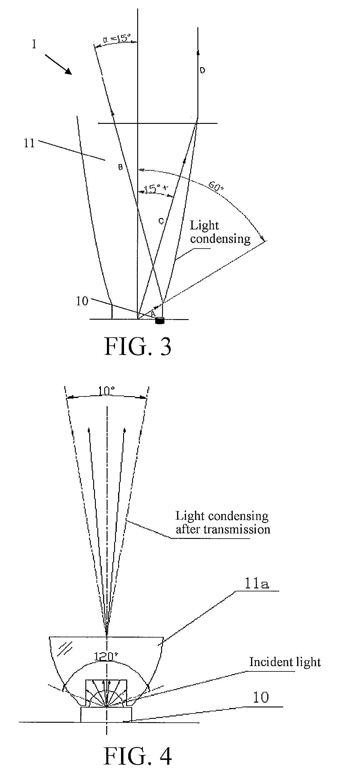
[0038]Referring to FIG. 3, a plurality of LEDs 10 is mounted and arranged on the substrate 1, and the condenser cup 11 is provided outside each of the LEDs 10. The condenser cup 11 may be separated from the substrate 1, or may be integrated with the substrate 1 in structure. An inner wall (that is, a curved wall) of the condenser cup 11 is designed to condense light rays emitted by the LED 10 to light rays with a beam angle falling within a certain range. The condensing principle of the condenser cup 11 is described below in d...

second embodiment

[0045]Referring to FIGS. 4 and 5, the LED lamp according to the present invention is further described below in detail.

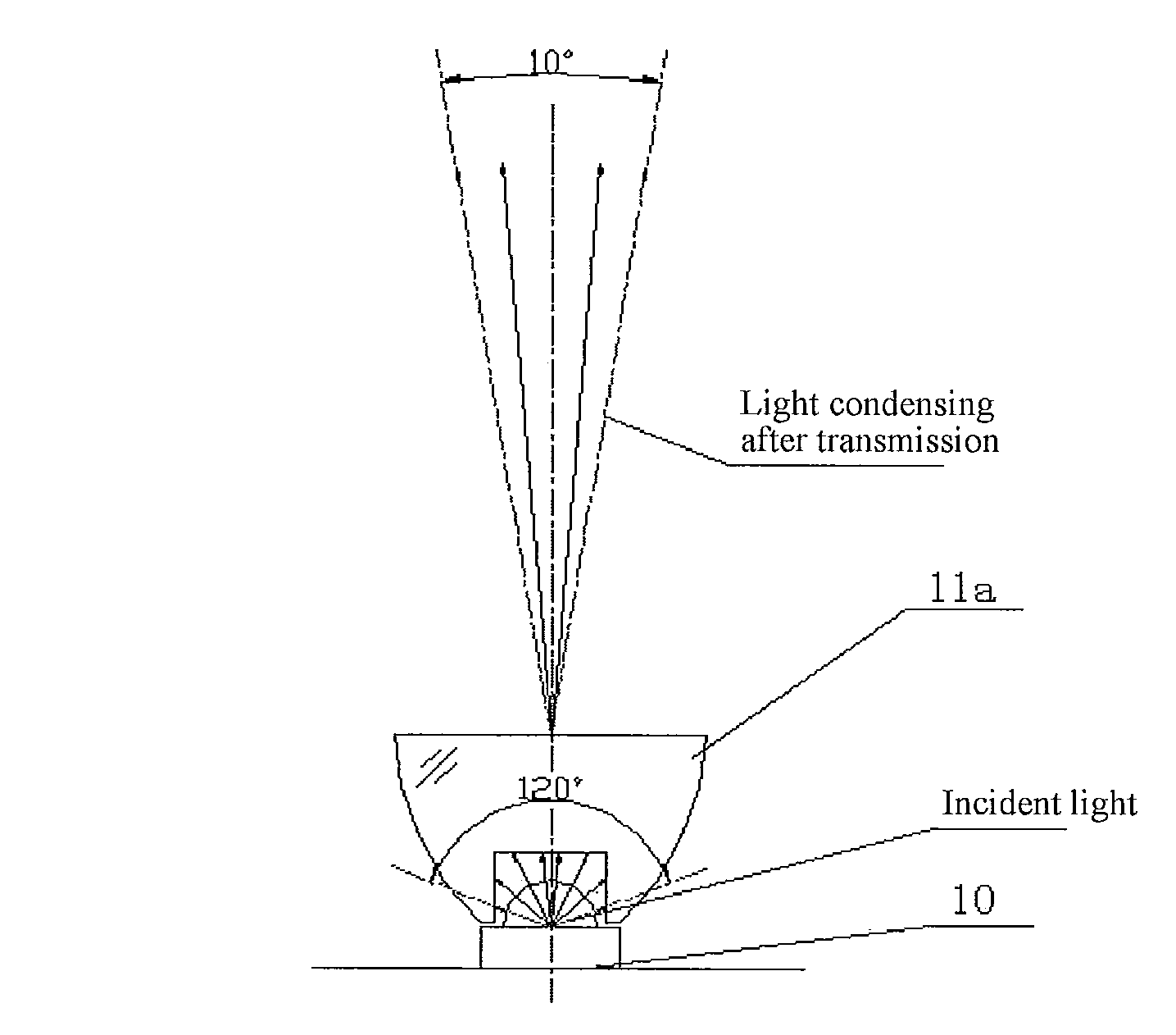
[0046]Referring to FIG. 4, a plurality of LEDs 10 is arranged on a substrate 1, and each LED 10 has a condenser lens 11a mounted on a front end thereof. The condenser lens 11a is preferably a cone-shaped or cup-shaped catadioptric lens, which is capable of performing transmission condensing right ahead, and a conical surface may collect all the side light and reflect the side light out, such that the overlapping of the two kinds of light (having the same angle) may obtain the perfect light ray utilization and desired light spot effect. The use of the condenser lens 11a may converge light emitting angles of the LED light sources, for example, a beam angle of an LED light source is about 120 degrees, and after passing through the condenser lens 11a, the beam angle may be converged to about 10 degrees.

[0047]In practice, the condenser lens 11a may be made of silica gel,...


PUM


Abstract

A light-emitting diode (LED) lamp and a street lamp using the same are provided. The LED lamp includes substrates for mounting LEDs, reflectors, radiators, a mounting frame, a power source, and a top cover. The substrates and the reflectors are mounted on the radiators. Each of the substrates has a condenser cup mounted around a light-emitting surface of the LED, and the condenser cup has a curved wall for condensing light rays emitted by the LED to a certain angle range; each of the reflectors has a curved surface for performing a second time reflection condensing on the light rays that are processed through the reflection condensing by the curved wall. The LED lamp realizes uniform lighting in the whole lighting range through performing reflection twice, thereby achieving excellent directivity of illumination, uniform brightness, eliminating the glare phenomenon, and achieving desirable heat dissipation performance.

Description

[0001]This application is a Continuation-In-Part of copending application Ser. No. 12 / 678,866 filed on Mar. 18, 2010. Application Ser. No. 12 / 678,866 is the national phase of PCT International Application No. PCT / CN2009 / 075830 filed on Dec. 22, 2009, and claims priority under 35 U.S.C. §119(a) to Patent Application No. 200910224095.4 filed in China, on Dec. 7, 2009, all of which are hereby expressly incorporated by reference into the present application.BACKGROUND OF THE INVENTION[0002]1. Field of Invention[0003]The present invention relates to a light-emitting diode (LED) lamp and a street lamp using the same, which belongs to the field of lighting technology.[0004]2. Related Art[0005]In the wide areas of outdoor roads and squares, conventional lighting lamps are high-pressure sodium lamps or metal halide lamps. The high-pressure sodium lamps or metal halide lamps have a luminous efficiency of 60-80 μm / W, and have a service life of about 6000 hours (h). Currently, the LED lamps hav...

Claims


Application Information

Patent Timeline
Patent Type & Authority Patents(United States)
IPC IPC(8): F21V7/00
CPCF21V7/0008F21V7/0025F21V29/74F21V7/048F21S2/005F21V5/04F21V7/0091F21W2131/103F21Y2101/02F21Y2105/001Y02B20/72F21Y2105/10F21Y2115/10
Inventor WANG, ZHEN
Owner WANG ZHEN
Why Eureka
Try Eureka