

Gas turbine engine systems and related methods involving vane-blade count ratios greater than unity
a technology of vane-blade count and gas turbine engine, which is applied in the direction of machines/engines, stators, liquid fuel engines, etc., can solve the problems of compromising the durability of high inlet temperature/high fuel-to-air ratio gas turbine engine designs
- Summary
- Abstract
- Description
- Claims
- Application Information
AI Technical Summary
Benefits of technology
Problems solved by technology
Method used
Image


Examples
Embodiment Construction
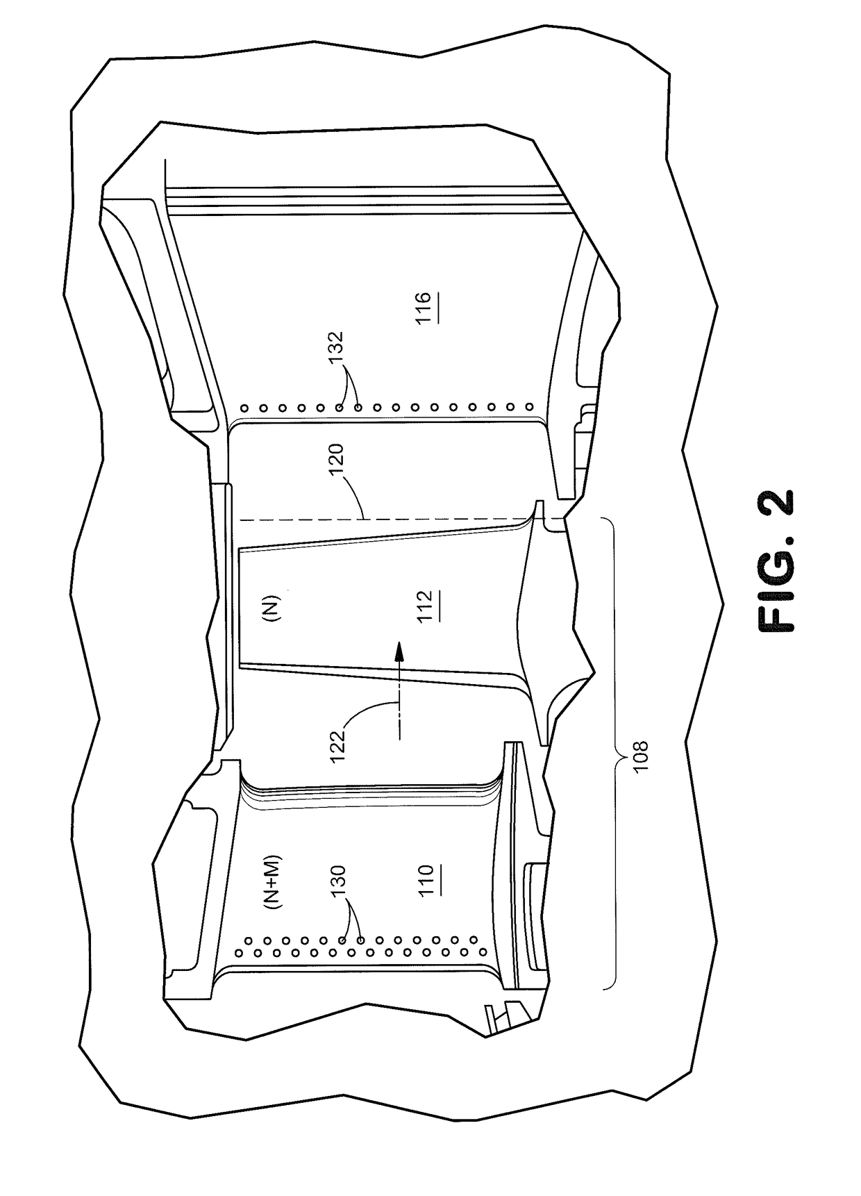
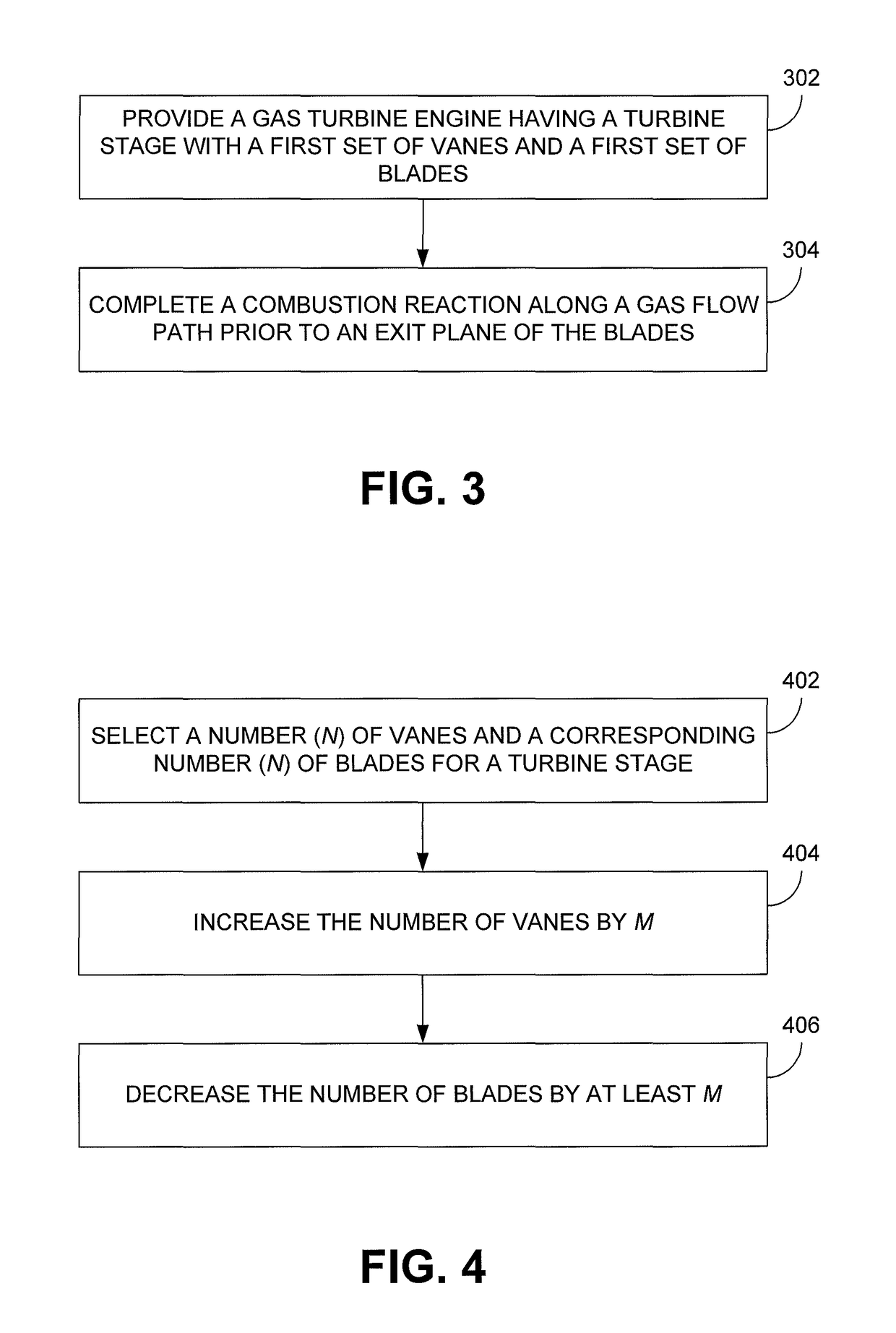
[0024]Gas turbine engine systems and related methods involving vane-blade count ratios greater than unity are provided, several exemplary embodiments of which will be described. In this regard, an increased vane count could increase the probability that a temperature / PPR's nonuniformity (“hot and / or fuel-rich streak”) will mix with cooler gases and, therefore, dissipate before propagating beyond the rotating blades of the first stage of the turbine. In some embodiments, the cooler gases used for dissipating such a hot streak are provided as cooling air, which is provided for film-cooling the vanes of the first turbine stage. In some embodiments, the vane and blade counts deviate from a nominal number so that overall parasitic drag and weight directly attributable to the vanes and blades are comparable to a gas turbine engine containing an equal number of vanes and blades. For example, in a first stage turbine design incorporating forty-eight (48) vanes and sixty-two (62) blades, the...
PUM
 Abstract
Description
Claims
Application Information