Power amplifier predistortion methods and apparatus

a technology of power amplifiers and distortion methods, applied in power amplifiers, digital transmission, secret communication, etc., can solve the problems of power amplifiers that cannot meet the requirements of most rf transmitters and receivers, power amplifiers with degraded output signal quality, and low power efficiency in the linear region

Active Publication Date: 2013-06-25
DALI SYST LTD
View PDF126 Cites 49 Cited by
  • Summary
  • Abstract
  • Description
  • Claims
  • Application Information

AI Technical Summary

Problems solved by technology

Setting a PA in the linear (amplifying) operation region of the PA will yield higher linear output characteristics, but operating with a bias in the linear region yields very low power efficiency.
Such degraded output signal quality cannot meet the requirements of most RF transmitters and receivers.
The non-linear operation of such power amplifiers causes distortion due to, among other things, what are referred to as intermodulation products in the output signal.
Such non-linear products are so close to the desired signal a...

Method used


Image

  • Power amplifier predistortion methods and apparatus
  • Power amplifier predistortion methods and apparatus

Examples


Embodiment Construction

[0010]The current and next-generation wireless communication systems will utilize improved PA efficiency technology for a variety of broadband and multimedia services, supported by an advanced wireless RF transmitter, in which a highly-efficient high power amplifier will provide substantially linear output to improve the transmitted quality and system performance while at the same time providing a cost savings both in terms of the equipment itself and the amount of power consumed during operation.

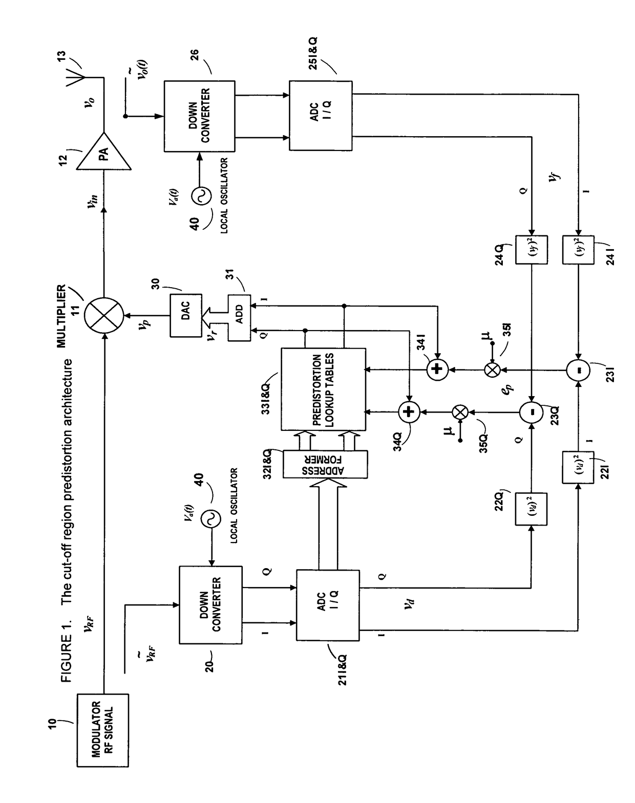
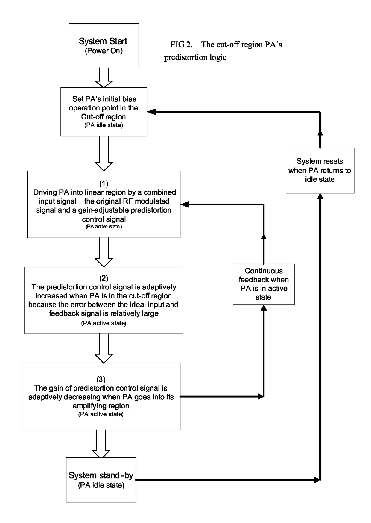
[0011]To provide improved performance, including minimizing DC power consumption, the present invention provides a power amplifier biased to operate initially in the cut-off region. However, biasing the power amplifier for initial operation in the cut-off region prevents the use of the conventional back-off linearization method, and a new predistortion solution is required. The solution of the present invention addresses both (i) the correction of the distortion in the cut-off region and (i...


PUM


Abstract

An embodiment of the invention is a predistortion approach to linearize a power amplifier by setting initially the static operation point of the power amplifier in the cut-off region. The architecture is based on the analog-digital combination by a multiplier and digital predistortion control circuit. The predistortion system generates an adaptive output signal to control the RF modulated signal that is the input signal of the power amplifier. The controlled and predistorted signal can contribute to drive a power amplifier with the cut-off static operation point into its amplifying region and simultaneously correct the non-linear distortion when the power amplifier operates to amplify an RF signal.

Description

RELATED CASES[0001]This application claims the benefit of U.S. Provisional Patent Application Ser. No. 60 / 876,640, filed Dec. 22, 2006, titled “POWER AMPLIFIER PREDISTORTION METHODS AND APPARATUS,” which is incorporated by reference in its entirety for all purposes. This application also is related to U.S. patent application Ser. No. 11 / 262,079, filed Oct. 27, 2005, and its parent, U.S. patent application Ser. No. 10 / 137,556, filed May 1, 2002, now U.S. Pat. No. 6,985,704, issued Jan. 10, 2006, as well as U.S. Provisional Patent Application Ser. No. 60 / 897,746, filed Jan. 26, 2007; Ser. No. 60 / 898,312, filed Jan. 29, 2007, Ser. No. 60 / 969,127, filed Aug. 30, 2007, Ser. No. 60 / 969,131, filed Aug. 30, 2007, and Ser. No. 60 / 012,416, filed Dec. 7, 2007, the disclosures of which are incorporated herein by reference in their entirety for all purposes.FIELD OF THE INVENTION[0002]In one aspect, the present invention relates to predistortion methods for linearizing the response of a power am...

Claims


Application Information

Patent Timeline
IPC IPC(8): H04B1/04
CPCH03F1/3247H03F3/189H03F3/24H04B2001/0425H03F2201/3233H03F2200/336H03F2201/3212H03F1/3241
Inventor YANG, DALI
Owner DALI SYST LTD
Why Eureka
Try Eureka