Laser cutting apparatus

a cutting device and laser cutting technology, applied in the field of cutting tools, can solve the problems of plastic particles affecting the obtained lens, affecting the image quality of the lens, and affecting the quality of the imag

Inactive Publication Date: 2013-07-02
HON HAI PRECISION IND CO LTD
View PDF14 Cites 2 Cited by
  • Summary
  • Abstract
  • Description
  • Claims
  • Application Information

AI Technical Summary

Benefits of technology

[0005]A simple way to separate each lens and the sprue is to cut off the lens from the sprue using a cutting tool (e.g., a scissor). However, a high shear force must be applied onto a periphery of the lens to cut off the lens, and the shear force may cause a stress concentration in the lens. As a result, the refractive index in different areas of the lens may become altered, and thereby an imaging quality of the lens is diminished. In addition, the cutting process may produce a plurality of small plastic waste particles, and these plastic particles are liable to pollute the obtained lens. Thus, an additional washing process is required. The washing process is time-consuming, and also decreases a yield rate of the lenses.

Problems solved by technology

However, a high shear force must be applied onto a periphery of the lens to cut off the lens, and the shear force may cause a stress concentration in the lens.
As a result, the refractive index in different areas of the lens may become altered, and thereby an imaging quality of the lens is diminished.
In addition, the cutting process may produce a plurality of small plastic waste particles, and these plastic particles are liable to pollute the obtained lens.
The washing process is time-consuming, and also decreases a yield rate of the lenses.

Method used


Image

  • Laser cutting apparatus
  • Laser cutting apparatus
  • Laser cutting apparatus

Examples


Embodiment Construction

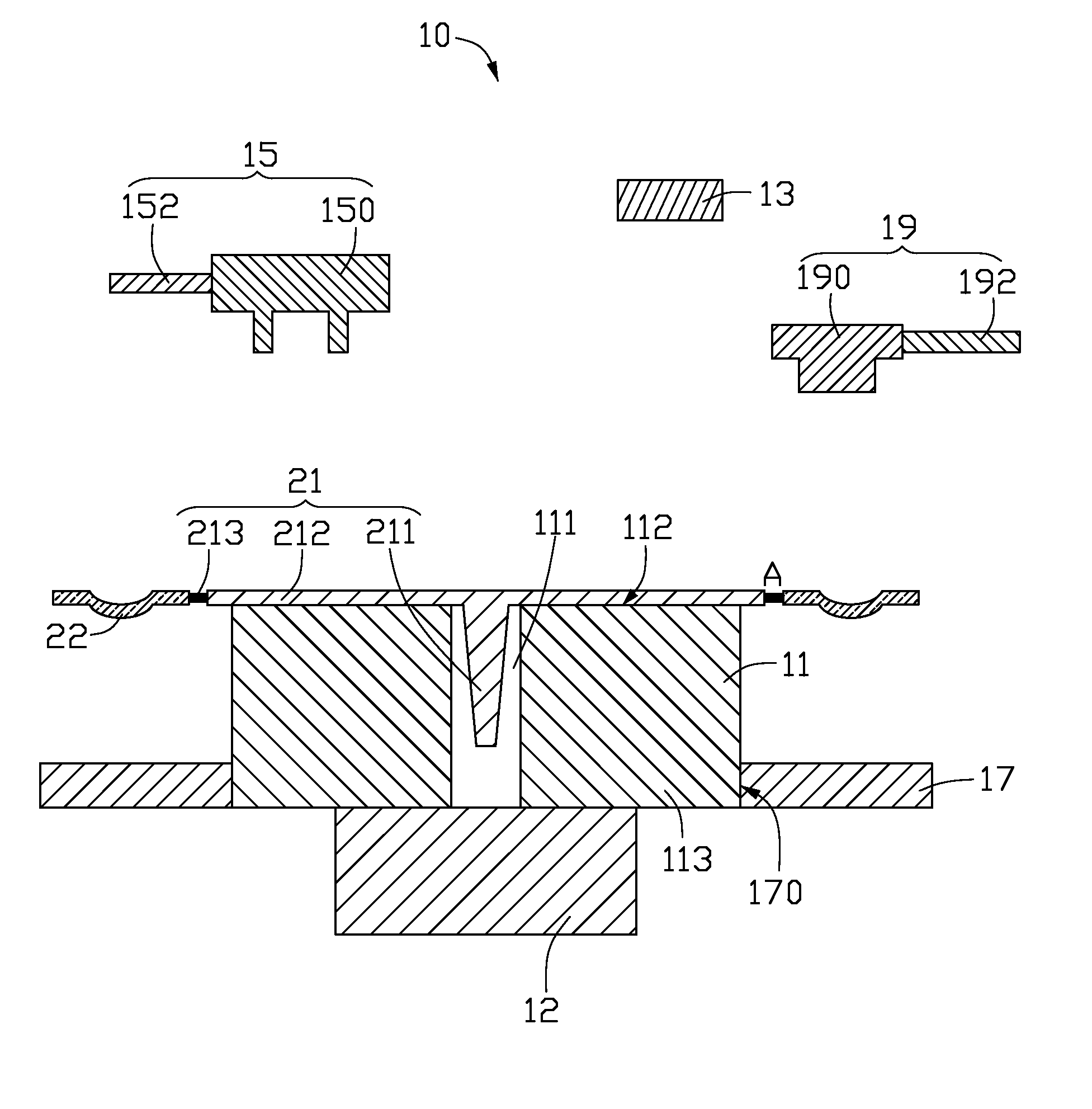
[0013]As shown in FIGS. 4A and 4B, a sprue 21 includes a main portion 211, four branch portions 212 perpendicularly extending from the main portion 211, and four sprue gate portions 213 respectively collinearly extending in a direction away from a corresponding branch portion 212. A lens 22 is formed at a distal end of each sprue gate portion 213. The branch portions 212 are angularly evenly arranged around the main portion 211. Thus, the four branch portions 212 constitute a cross-like structure.

[0014]Typically, the sprue 21 with lenses 22 is made using an injection mold. It is understood that the structure of the sprue 21 corresponds to a runner system in an injection mold. For example, after a cooling process, the plastic in the main runner forms the main portion 211, the plastic in the branch runners forms the branch portions 212, and the plastic in the sprue gate forms the sprue gate portions 213.

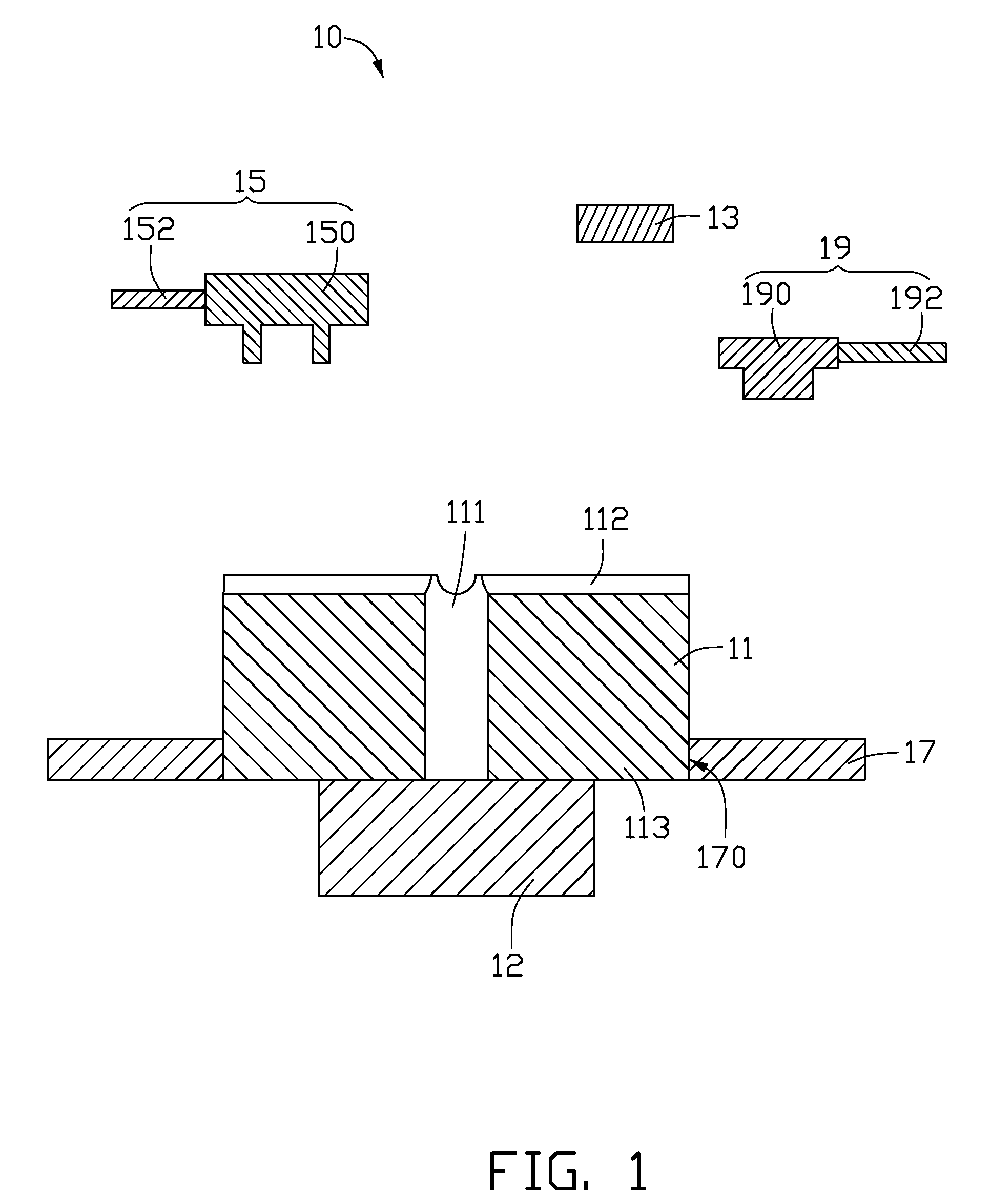
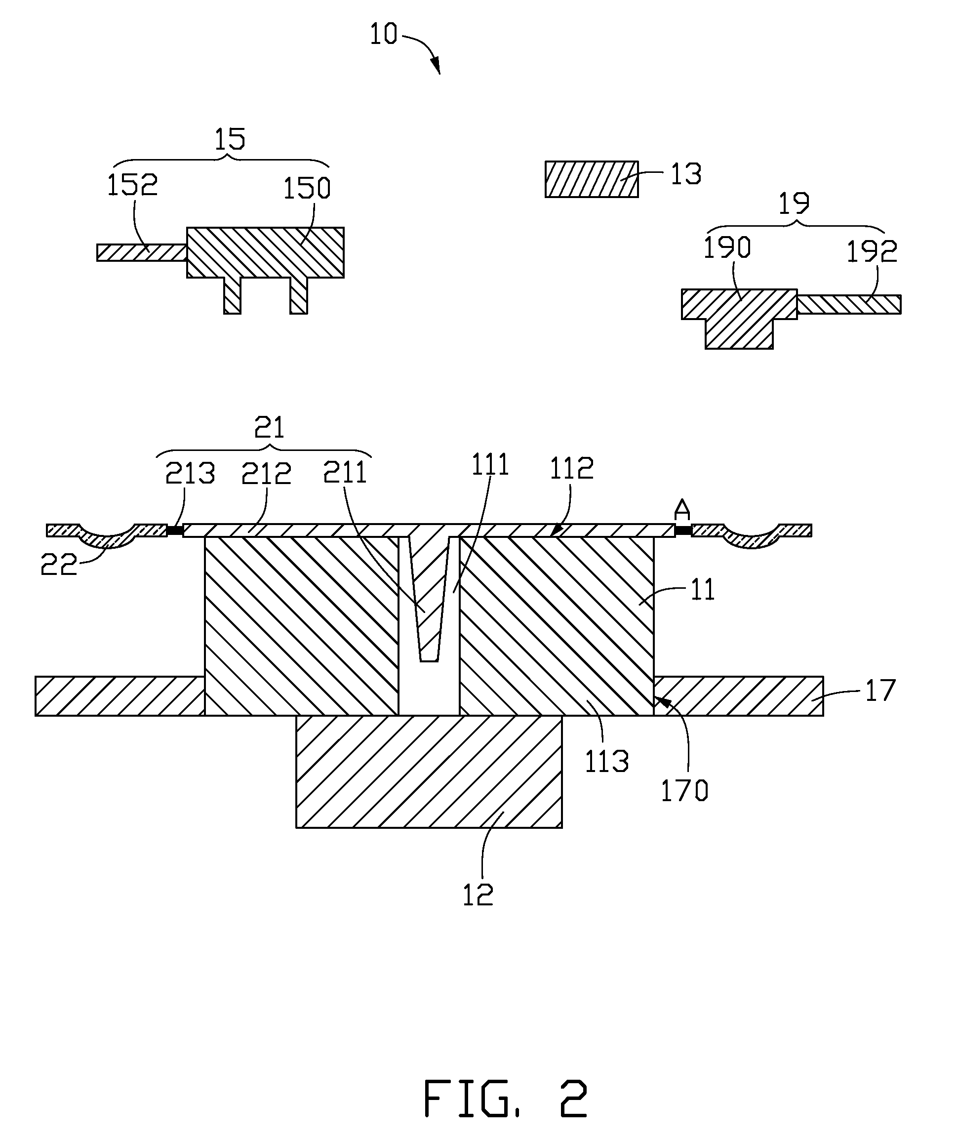
[0015]Referring also to FIGS. 1 and 2, a cutting apparatus 10 in accordance with o...


PUM

PropertyMeasurementUnit
circumferenceaaaaaaaaaa
diameteraaaaaaaaaa
areaaaaaaaaaaa

Abstract

An exemplary cutting apparatus for cutting components from a sprue includes a sprue retainer, a laser cutting unit, and a rotating driving unit. The sprue retainer has a supporting surface. The supporting surface defines a receiving hole, and grooves extending across the entire supporting surface. The grooves are in communication with the receiving hole. The laser cutting unit is disposed above the sprue retainer and is configured for emitting a laser beam to cut the sprue carried on the sprue retainer. The sprue retainer is coupled to the rotating driving such that the rotating driving unit is capable of driving the sprue retainer to rotate.

Description

BACKGROUND[0001]1. Technical Field[0002]The present invention relates to cutting apparatuses, and particularly to a cutting apparatus for cutting components from a sprue.[0003]2. Related Art[0004]Nowadays, plastic lenses are becoming more and more popular, particular in micro imaging apparatuses (e.g., lens modules widely used in mobile phones). This is due in large part to plastic lenses being highly suitable for mass production, enabling simple manufacturing processes and low manufacturing costs. Generally, plastic lenses are made using an injection molding process. To improve manufacturing efficiency, an injection mold may include two, fourth, eight or even more molding cavities for molding multiple plastic lenses in a single cycle. Such injection mold needs a multi-branch passage for providing molten plastic to the molding cavities. After a molding process, the plastic in the molding cavities forms a number of lenses. However, the plastic in the multi-branch passage is also soli...

Claims


Application Information

Patent Timeline
Patent Type & Authority Patents(United States)
IPC IPC(8): B23K26/02B29D11/00B28B11/12
CPCB23K26/0823B23K26/4065B29C45/38B29D11/00432B29C2045/0094B29L2011/0016B23K2103/42B23K2103/50
Inventor TUNG, TSAI-SHIH
Owner HON HAI PRECISION IND CO LTD
Why Eureka
Try Eureka