Optical encoder

an encoder and optical technology, applied in the field of optical encoders, can solve the problems of large size of photoelectric encoder, large scale and light receiving element cannot be arranged in parallel, and achieve the effect of reducing the unevenness of light emitted and performing accurate measuremen

Active Publication Date: 2013-07-02
MITUTOYO CORP
View PDF9 Cites 44 Cited by
  • Summary
  • Abstract
  • Description
  • Claims
  • Application Information

AI Technical Summary

Benefits of technology

[0012]In this configuration, since the optical axis of the light source is separated from the optical axis of the scale-side lens by a predetermined distance in the direction perpendicular to a reading direction of the scale markings (hereinafter, referred to as a direction perpendicular to the scale markings), the illumination light emitted from the light source is transmitted to the scale through a light source-side of the scale-side lens in a direction perpendicular to the scale markings. In addition, this light is reflected by the scale and received by the light receiving element through a side of the scale-side lens opposite to the light source-side in a direction perpendicular to the scale markings Therefore, according to the present invention, it is possible to separate the optical path of the light emitted from the light source and directed toward the scale from the optical path of the light reflected by the scale and directed toward the light receiving element through the scale-side lens without using a half-mirror. Therefore, it is possible to obtain a sufficient amount of light in the light receiving element.
[0031]In this configuration, since it is possible to reduce unevenness of the light emitted from the light source and directed toward the scale through the scale-side lens, it is possible to perform accurate measurement.

Problems solved by technology

However, in the photoelectric encoder disclosed in Patent Document 2, the scale and the light receiving element cannot be arranged in parallel.
Therefore, there is a problem in that the photoelectric encoder becomes large in size.
However, in this photoelectric encoder, since four lenses are arranged between the scale and the light receiving element, there is a problem in that the photoelectric encoder becomes large in size.

Method used


Image

  • Optical encoder
  • Optical encoder
  • Optical encoder

Examples


first embodiment

[0042]Hereinafter, a first embodiment of the present invention will be described with reference to the accompanying drawings.

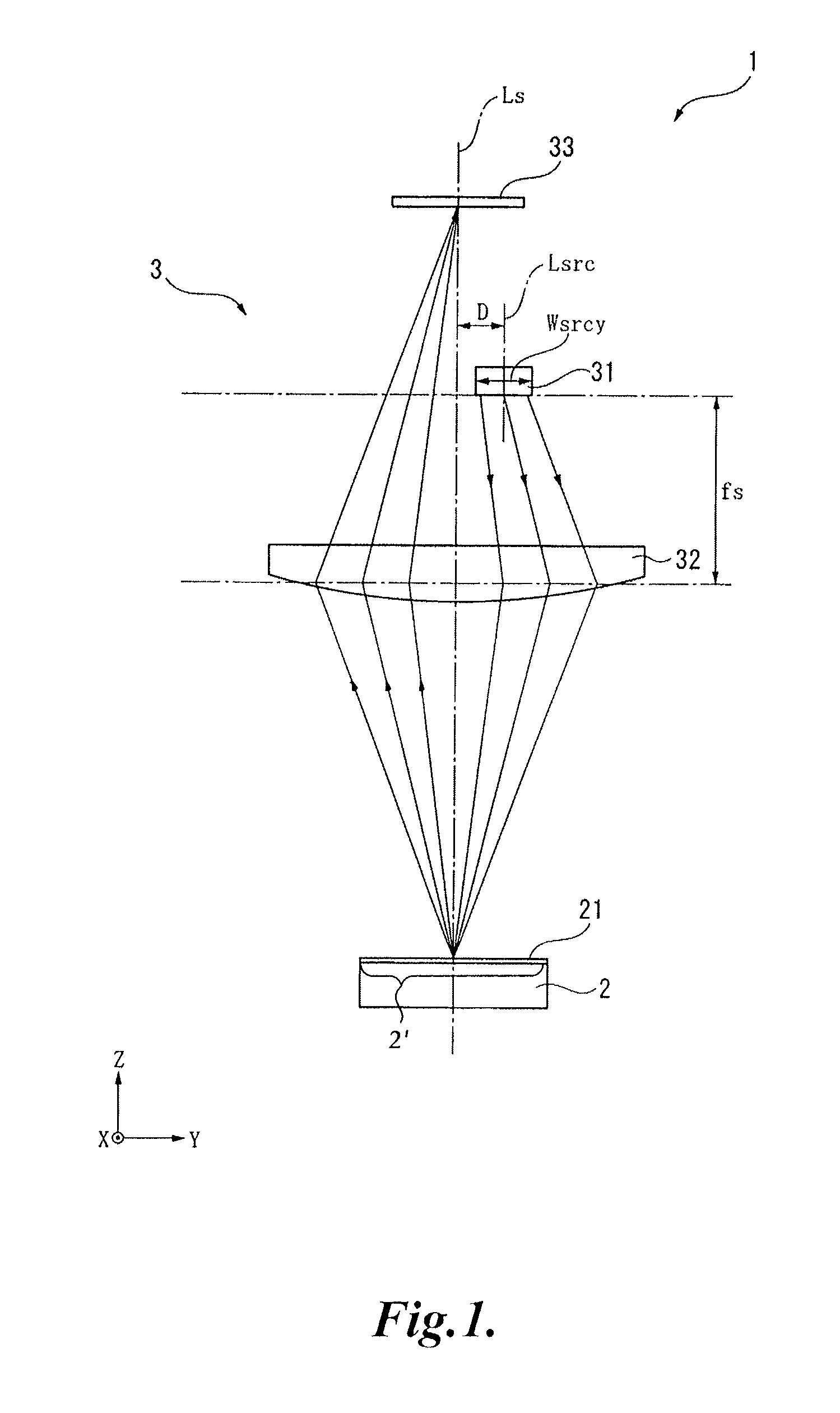
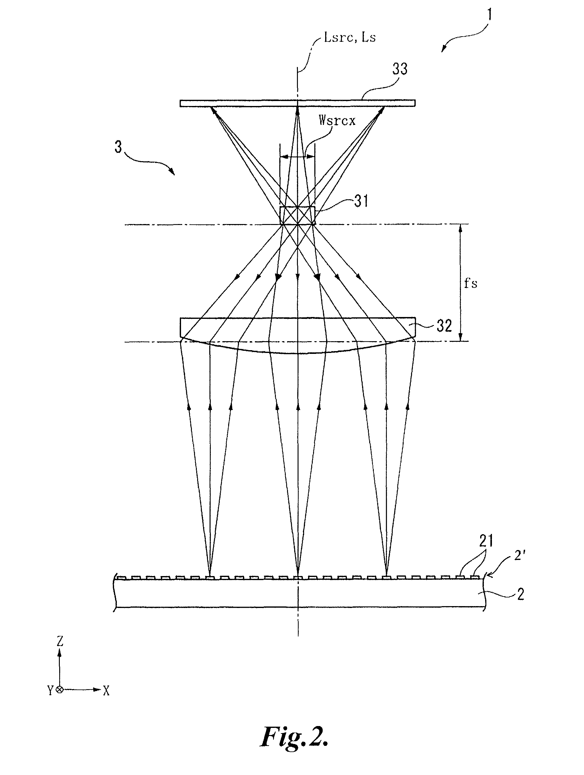
[0043]FIG. 1 is a schematic diagram illustrating an optical encoder 1 according to a first embodiment of the present invention. In FIG. 1, the X axis denotes an axis normal to a paper plane, the Y axis denotes an axis extending in a horizontal direction, and the Z axis denotes an axis extending in a vertical direction.

[0044]Referring to FIGS. 1 and 2, the optical encoder 1 includes a scale 2 having latticed or striped scale markings 21 that can be read along the X-axis direction and a readhead 3 having a light source 31 which emits light to the scale 2, a scale-side lens 32 which transmits the light from the light source 31 to the scale 2, and a light receiving element 33 which is arranged in parallel with the scale 2 and receives the light that has been reflected by the scale 2 and has passed through the scale-side lens 32 so that the position of the readhead...

second embodiment

[0059]Hereinafter, a second embodiment of the present invention will be described with reference to the accompanying drawings. In the following descriptions, like reference numerals denote like elements as in the aforementioned embodiment, and descriptions thereof will not be repeated.

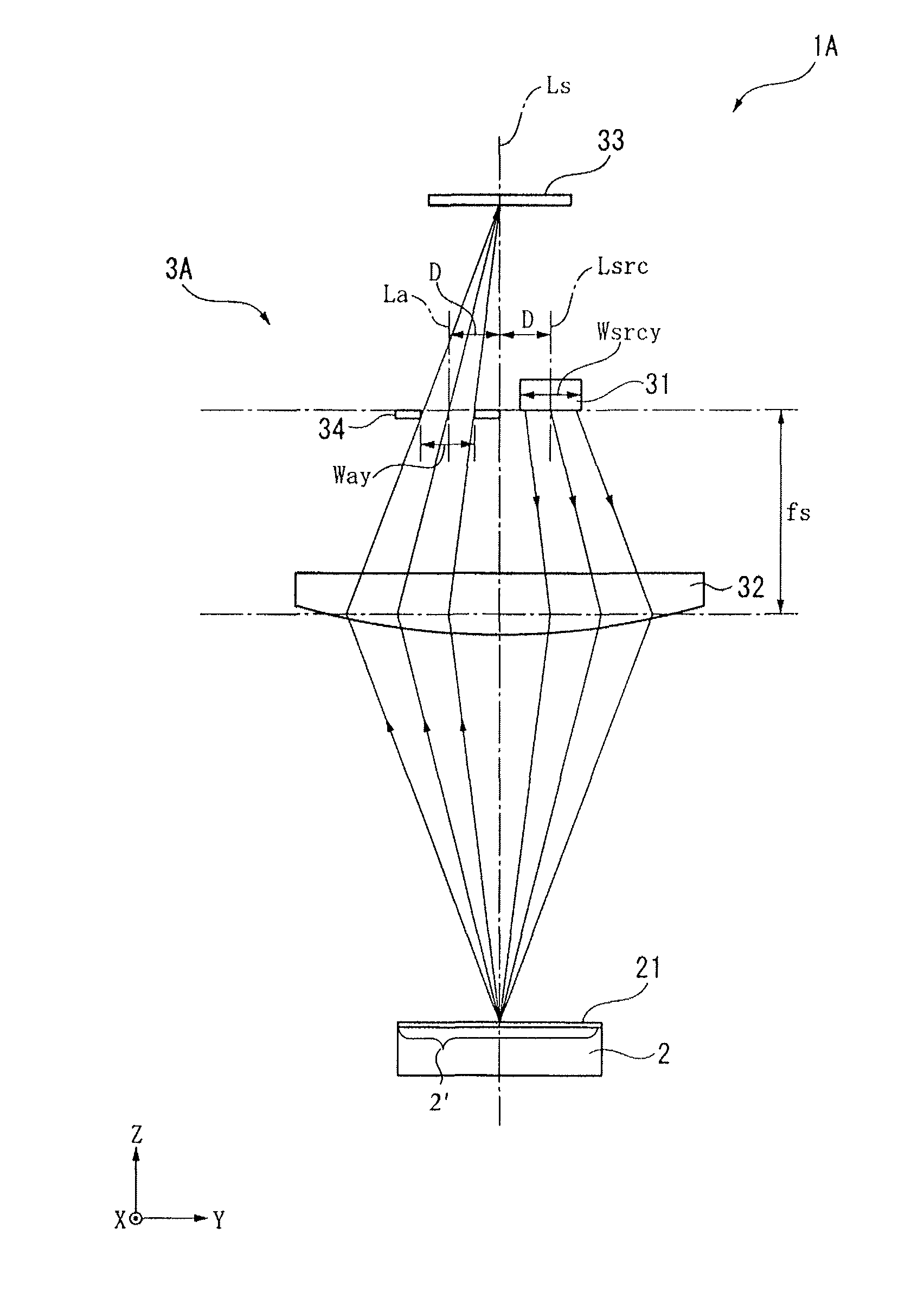
[0060]FIG. 3 is a schematic diagram illustrating the optical encoder 1A as seen in a reading direction of the scale markings 21 (X direction) according to the second embodiment of the present invention. FIG. 4 is a schematic diagram illustrating the optical encoder 1A as seen in the Y direction perpendicular to the scale markings 21.

[0061]In the first embodiment, the optical encoder 1 includes the readhead 3 having the light source 31, the scale-side lens 32, and the light receiving element 33. On the other hand, in the present embodiment, the readhead 3A of the optical encoder 1A further includes an aperture 34 in addition to the light source 31, the scale-side lens 32, and the light receiving element...

third embodiment

[0073]FIG. 5 is a schematic diagram illustrating an optical encoder 1B as seen in the X reading direction of the scale markings 21 according to a third embodiment of the present invention. FIG. 6 is a schematic diagram illustrating the optical encoder 1B as seen in the Y direction perpendicular to the scale markings 21.

[0074]In the second embodiment, the optical encoder 1A includes the readhead 3A having the light source 31, the scale-side lens 32, the light receiving element 33, and the aperture 34. On the other hand, in the present embodiment, the optical encoder 1B includes the readhead 3B having a light receiving element-side lens 35 in addition to the light source 31, the scale-side lens 32, the light receiving element 33, and the aperture 34 as shown in FIGS. 5 and 6.

[0075]The light receiving element-side lens 35 is arranged between the aperture 34 and the light receiving element 33. The distance between the aperture 34 and the light receiving element-side lens 35 is set to be...


PUM


Abstract

A miniaturized optical encoder capable of obtaining a sufficient amount of light in the light receiving element is provided. An optical encoder 1 includes a scale 2 having scale markings 21 and a readhead 3 having a light source 31 that emits light to the scale 2, a scale-side lens 32 that transmits the light emitted from the light source 31 to the scale 2, and a light receiving element 33 that receives the light that has been reflected by the scale 2 and that has passed through the scale-side lens 32. The light source 31 is arranged between the scale-side lens 32 and the light receiving element 33, and a distance between the light source 31 and the scale-side lens 32 is set to be a focal distance fs of the scale-side lens 32. An optical axis Lsrc of the light source 31 is matched with an optical axis Ls of the scale-side lens 32 in a reading direction of the scale markings 21 and is separated from an optical axis Ls of the scale-side lens 32 by a predetermined distance D in a direction perpendicular to the reading direction of the scale markings 21.

Description

BACKGROUND[0001]1. Technical Field[0002]The present invention relates to an optical encoder.[0003]2. Description of the Related Art[0004]In the related art, there is known an optical encoder including a scale having latticed or striped scale markings and a readhead, which has a light source that emits light to the scale and a light receiving element that receives the light reflected by the scale, so that the position of the readhead with respect to the scale is measured based on the light received by the light receiving element. Some sample optical encoders are disclosed in Japanese Patent Application Publication Nos. 2003-307440 (“Patent Document 1”) and 2006-284564 (“Patent Document 2”).[0005]The optical encoder disclosed in Patent Document 1 includes scale markings (a scale) and a reflection type optical reader (a readhead) having a light-emitting diode (a light source), an object lens, and a light receiving unit (a light receiving element). In addition, the reflection type optic...

Claims


Application Information

Patent Timeline
Patent Type & Authority Patents(United States)
IPC IPC(8): G01D5/34
CPCG01D5/34715
Inventor NAGAHAMA, TATSUYAMIZUTANI, MIYAKOYAKU, TORU
Owner MITUTOYO CORP
Why Eureka
Try Eureka