Check patentability & draft patents in minutes with Patsnap Eureka AI!

Compression driver and horn structure

a compression driver and horn technology, applied in the direction of transducer details, electrical transducers, deaf-aid sets, etc., can solve the problems of horn no longer being able to radiate any appreciable acoustic power, radiation pattern no longer constant, overall horn/driver efficiency is substantially reduced, etc., to achieve wider beam width, wide spread, and reduced dispersion angle

Active Publication Date: 2013-07-02
ONEILL ROBERT M
View PDF4 Cites 3 Cited by
  • Summary
  • Abstract
  • Description
  • Claims
  • Application Information

AI Technical Summary

Benefits of technology

This design enhances the high frequency dispersion and beamwidth, allowing for wider dispersion patterns and improved directional control, with measured improvements in the Equivalent Throat driver / horn combination compared to conventional systems.

Problems solved by technology

When the radiated wavelengths become large compared to the length and mouth circumference, the horn is no longer able to radiate any appreciable acoustic power and the overall horn / driver efficiency is substantially reduced.
If the radiated directivity, or beamwidth, becomes less than the included angles of the horn, then the radiation pattern is no longer constant and the wave front radiated by the driver is no longer controlled by the included angles of the horn.
This increase in the radius then limits the ability of the driver to produce a wide dispersion and broad radiation pattern as frequency is increased.

Method used


Image

  • Compression driver and horn structure
  • Compression driver and horn structure
  • Compression driver and horn structure

Examples


Embodiment Construction

[0075]Before explaining exemplary embodiments and methods of the present invention in detail (as illustrated in FIGS. 2B-24C), it is to be understood that the invention is not limited in its application to the details of construction and to the arrangements of the components set forth in the following description or illustrated in the Figures. The invention is capable of other embodiments and of being practiced and carried out in various ways. Also, it is to be understood that the phraseology and terminology employed herein are for the purpose of description and should not be regarded as limiting.

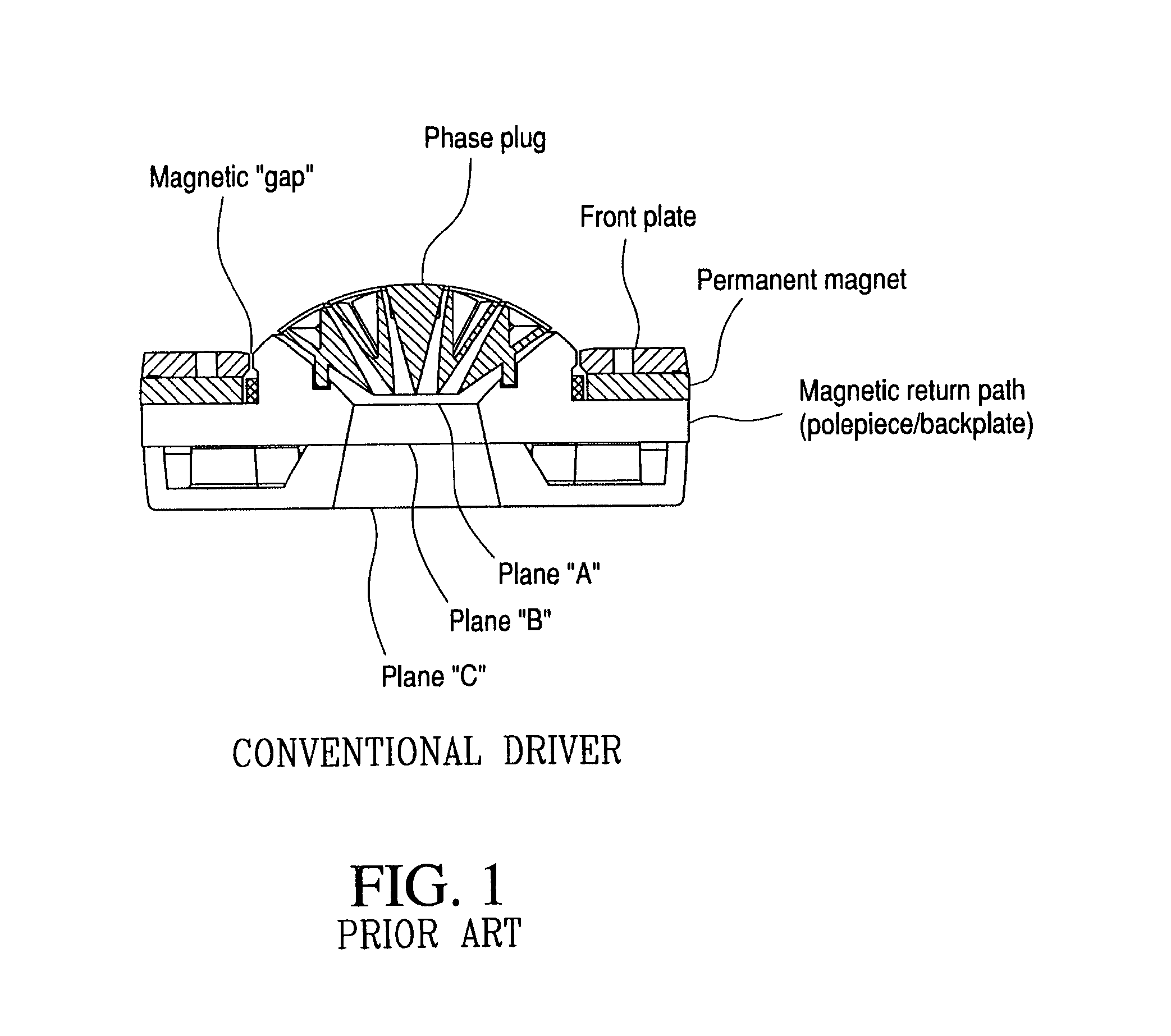
[0076]Returning to the background discussion on a horn's throat, applicant's study of FIG. 1 prompted applicant to explore whether the most ideal location for a throat with a minimized radius is at the location shown in the drawing as plane “A”, where the cross sectional area is the smallest and, as a result, the radius is minimal for any given design.

[0077]There is no specific radius or as...


PUM


Abstract

A loudspeaker driver 100 with new horn throat configuration 120 has a phase plug summation plane radius that is also the effective throat of the driver. The selected plane “D” where the elements of the horn that provide directional information to the wave front are implemented is made part of the geometry of the magnetic return circuit back plate 108. The portion of the back plate that is coincident with the selected plane “D” has a lumen or opening that is made equal to the radius of the circle defined by the phase plug summation plane. The geometry of the back plate's lumen controls projected sound's radiation pattern.

Description

PRIORITY CLAIMS AND REFERENCE TO RELATED APPLICATIONS[0001]This is a Continuation application which claims priority under 35 U.S.C. 120 and 35 U.S.C. 111(a) as the U.S. National Phase under 35 USC 371 of PCT / US2008 / 003123, filed Mar. 10, 2008; published, in English, as WO 2008 / 112175 on Sep. 18, 2008 and also claims priority to U.S. provisional patent application 60 / 905,912 tiled Mar. 9, 2007, the entire disclosures of which are expressly incorporated herein by reference.BACKGROUND OF THE INVENTION[0002]1. Technical Field of the Invention[0003]The present invention relates to electromechanical transducer structures and, more particularly, to loudspeaker compression driver and horn structures.[0004]2. Description of the Background Art[0005]Conventional prior art audio frequency reproduction systems use transducers to convert electrical energy to acoustical energy. Systems used for the reinforcement of speech and music are referred to as Sound Reinforcement Systems. These systems are ...

Claims


Application Information

Patent Timeline
Patent Type & Authority Patents(United States)
IPC IPC(8): H04R25/00
CPCH04R9/02
Inventor O'NEILL, ROBERT M.
Owner ONEILL ROBERT M
Features
  • R&D
  • Intellectual Property
  • Life Sciences
  • Materials
  • Tech Scout
  • Unparalleled Data Quality
  • Higher Quality Content
  • 60% Fewer Hallucinations
Learn More