Approximate calculation of 2D matrix entries via GPU
Active Publication Date: 2013-07-02
D2S
View PDF4 Cites 7 Cited by
- Summary
- Abstract
- Description
- Claims
- Application Information
AI Technical Summary
Benefits of technology
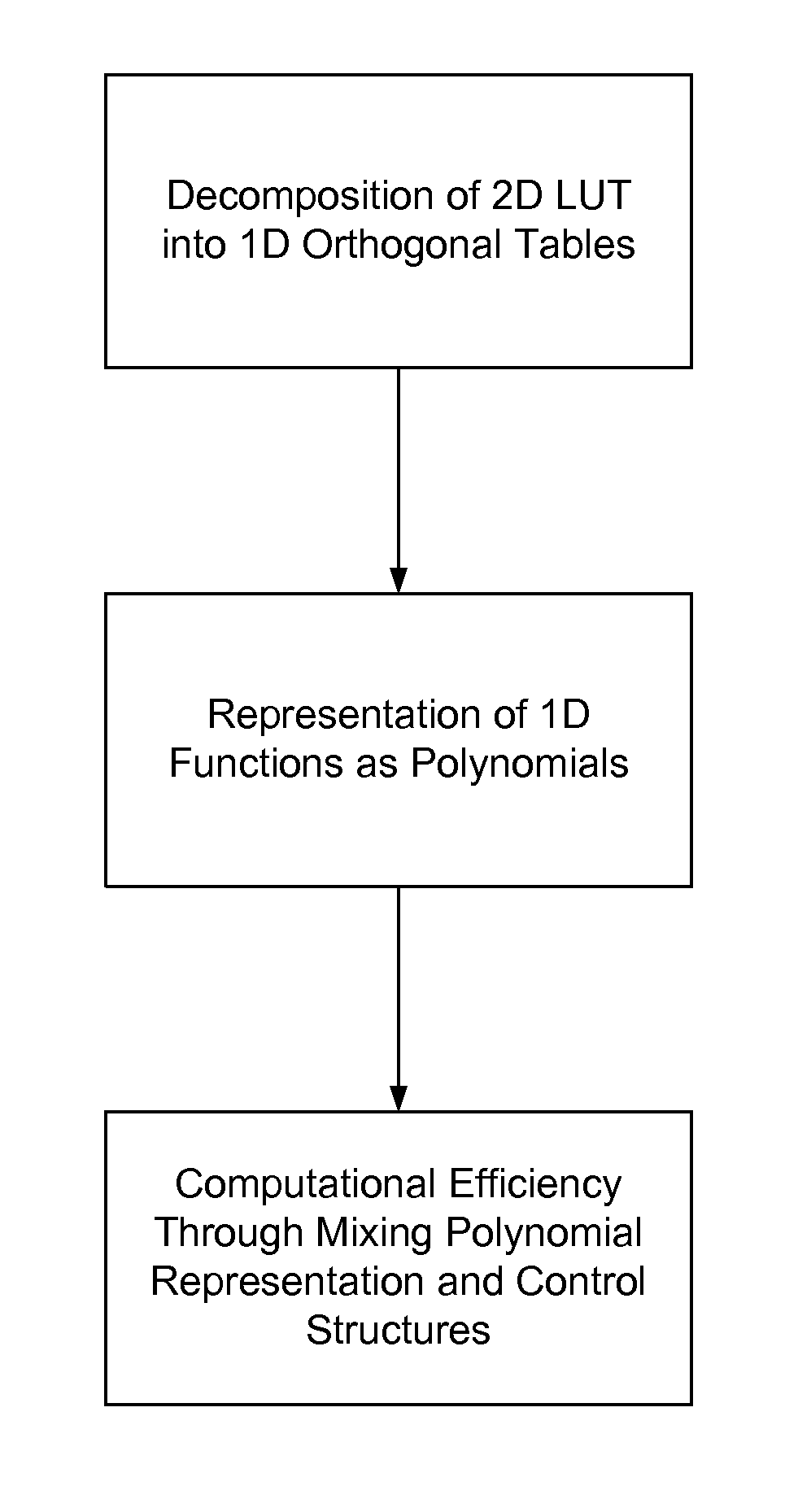
The invention is a technique to minimize memory access in matrix computations by converting them into a set of low-order polynomials. This set of polynomials is then processed using parallel computational hardware, such as graphics processing units, to achieve efficient computation. The invention also includes rules to reduce the complexity of the computations and methods for determining the necessary order of polynomials to achieve a desired accuracy target. The invention can be applied in various fields, such as lithography and signal processing, and can optimize memory access for efficient computation.
Problems solved by technology
With the above approach, the computational burden is replaced with increased communication with the memory.
In the cases where these tables cannot fit into fast-speed memories such as L1 cache, the frequent access to these tables significantly slow down the computational speed.
Method used
View moreImage
Smart ImageViewing Examples
Examples
case 1
[0057][0058]hnk1=((c3*x+c2)*x+c1)*x+c0;
[0059]break; case 2:[0060]hnk1=((c7*x+c6)*x+c5)*x+c4;
[0061]break;
[0062]. . .
[0063]}
[0064]In other words, the total cost can be reduced to 8*(4+1)=40 computations. Therefore, this computation is about five times faster than a computation employing memory lookup operations.
Login to View More PUM
 Abstract
Minimizing memory access by converting a given matrix computation into a set of low-order polynomials. The low-order polynomials can be used by dividing the domain of the polynomials into smaller subregions. If the domain is divided into equal intervals, the low-order polynomial can be used to approximate results from the matrix computation. The set of polynomials is processed using parallel computational hardware such as graphical processing units.
Description
CROSS-REFERENCE TO RELATED APPLICATION[0001]This patent application claims the benefit of U.S. provisional patent application 60 / 862,362, filed Oct. 20, 2006, which is incorporated by reference along with all other references cited in this application.BACKGROUND OF THE INVENTION[0002]This invention relates to the field of scientific computation and in particular, to techniques of using parallel computational hardware such as graphical processing units in scientific computation.[0003]In scientific computations, such as physics and image processing, two-dimensional (2D) matrix representations are commonly implemented as lookup tables (LUTs). The main motivation with such approach is to be able to calculate a finite set of values beforehand and store in the memory to avoid real-time computations.[0004]With the above approach, the computational burden is replaced with increased communication with the memory. In the cases where these tables cannot fit into fast-speed memories such as L1 ...
Claims
Login to View More Application Information
Patent Timeline
 IPC IPC(8): G06F7/38
CPCG06F17/16G06F17/175G06F30/398
Inventor TORUNOGLU, ILHAMI H.
Owner D2S
Features
- R&D
- Intellectual Property
- Life Sciences
- Materials
- Tech Scout
- Unparalleled Data Quality
- Higher Quality Content
- 60% Fewer Hallucinations
Learn More Browse by: Latest US Patents, China's latest patents, Technical Efficacy Thesaurus, Application Domain, Technology Topic, Popular Technical Reports.
© 2025 PatSnap. All rights reserved.Legal|Privacy policy|Modern Slavery Act Transparency Statement|Sitemap|About US| Contact US: help@patsnap.com


