Secure high-throughput data-center network employing routed firewalls

a high-throughput, firewall technology, applied in the field of network architecture, can solve the problems of inability to secure high-throughput data-center networks, etc., to achieve the effect of avoiding traffic bottlenecks, reducing the risk of traffic congestion, and avoiding traffic congestion

Active Publication Date: 2013-07-02
CISCO TECH INC
View PDF9 Cites 40 Cited by
  • Summary
  • Abstract
  • Description
  • Claims
  • Application Information

AI Technical Summary

Problems solved by technology

Unfortunately, existing data-center network designs often require tradeoffs between security capabilities, bandwidth, and scalability.
Consequently, conventional data

Method used


Image

  • Secure high-throughput data-center network employing routed firewalls
  • Secure high-throughput data-center network employing routed firewalls
  • Secure high-throughput data-center network employing routed firewalls

Examples


Embodiment Construction

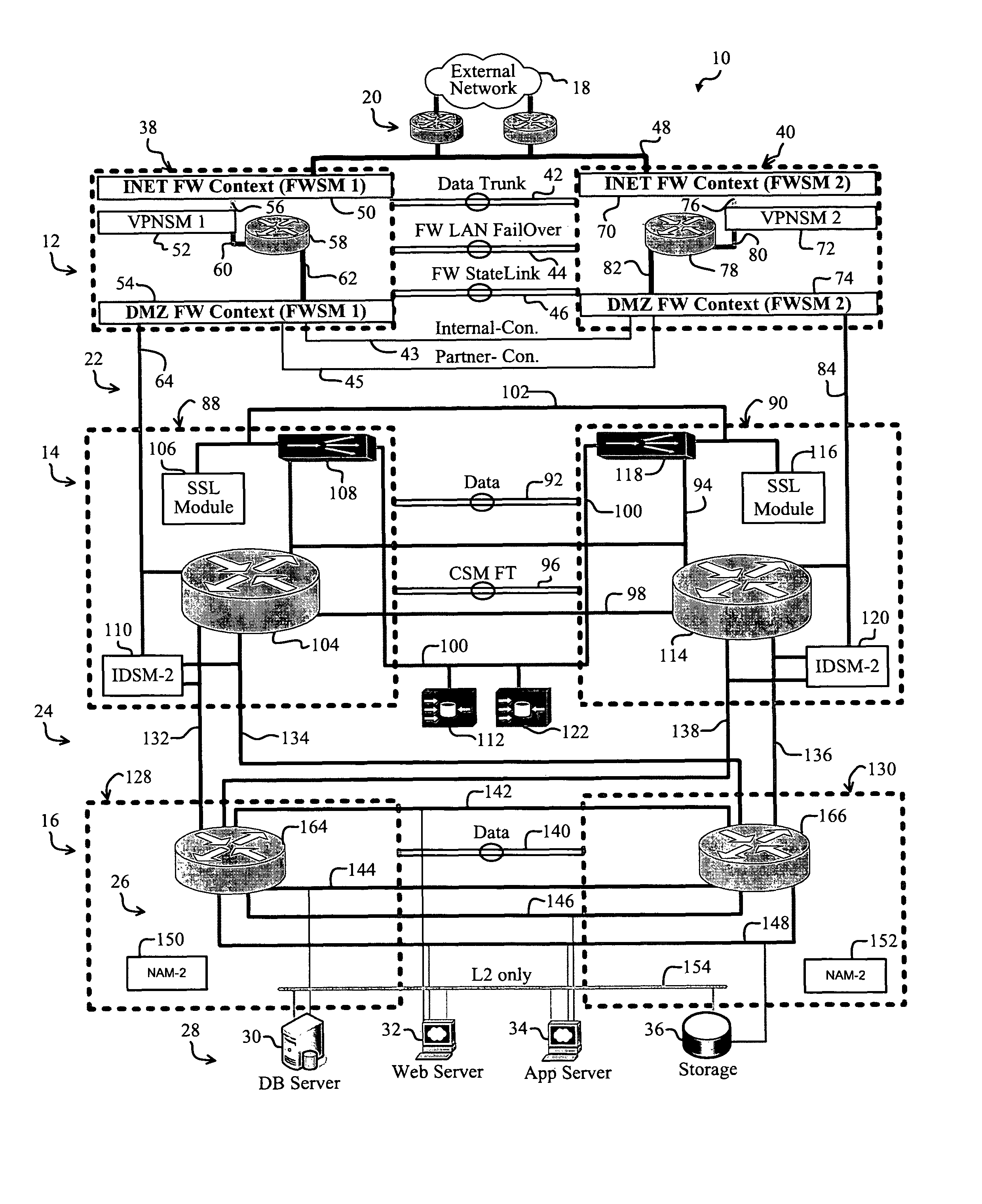
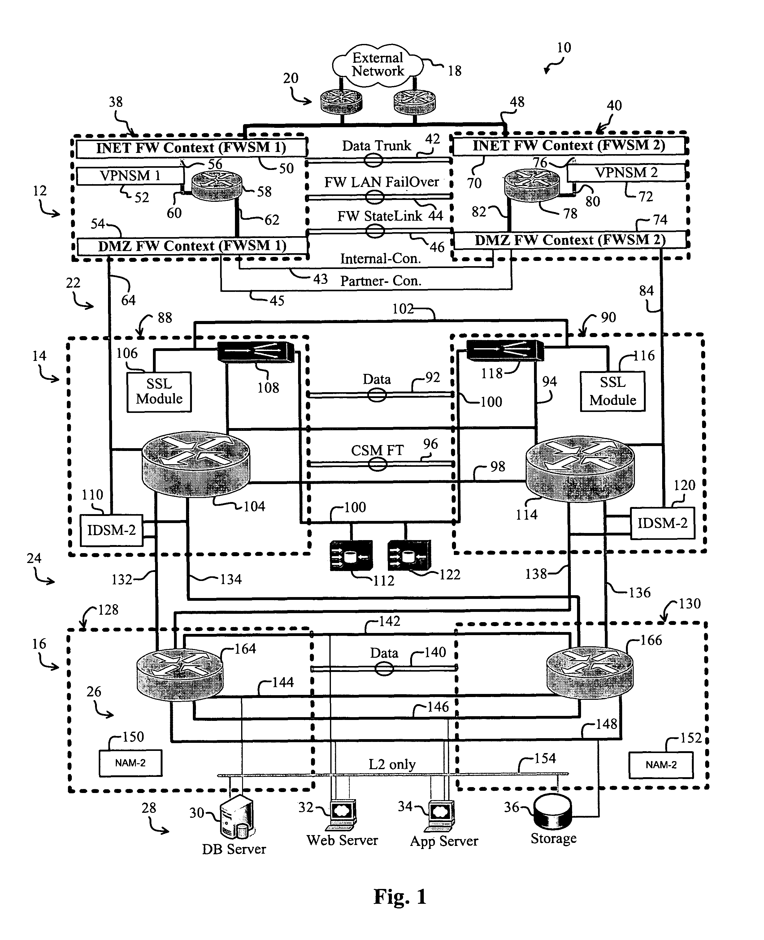
[0007]A preferred embodiment of the present invention implements a data-center network. In a specific embodiment, the data center includes a first data-center tier that that connects to an external network and to an internal portion of the data center. A first firewall instance interfaces the first tier and the external network. A second firewall instance interfaces the first tier and the internal portion of the data center. The data center reliably incorporates essential data center components in a secure, scalable, and redundant fashion.

[0008]For clarity, various well-known components, such as power supplies, modems, network blades, Service Providers (ISPs), browsers, standby modules, and so on, have been omitted from the figures. However, those skilled in the art with access to the present teachings will know which components to implement and how to implement them to meet the needs of a given application.

[0009]FIG. 1 is a diagram of a data-center network, i.e., a data center 10, ...


PUM


Abstract

A reliable and secure data-center. The data center includes a first data-center tier that is adapted to connect to an external network and an internal portion of the data center. A first firewall instance interfaces the first tier and the external network. A second firewall instance interfaces the first tier and the internal portion of the data center. In a more specific embodiment, the first firewall instance and the second firewall instance accommodate Internet Protocol SECurity (IPSEC) terminations using one or more VPNSMs. In this embodiment, the first data-center tier implements a core tier that includes one or more core switches that facilitate implementing the first firewall instance and the second firewall instance. The interior portion of the network represents a DeMilitarized Zone (DMZ) that includes a second tier that is connected between the first data-center tier and a third tier. The second tier implements an aggregation tier that includes one or more aggregation switches that facilitate implementing reverse-proxy caching. Overall Layer-3 design methodology is used within each tier and across tiers for optimized packet switching. The aggregation tier includes one or more aggregation-tier service modules for implementing load balancing, Secure Socket Layer (SSL) offloading, and/or the reverse-proxy caching.

Description

BACKGROUND OF THE INVENTION[0001]This application is related to co-pending U.S. patent application Ser. No. 11 / 227,377 entitled “Data-Center Network Architecture”, filed on Sep. 14, 2005, which is hereby incorporated by reference as if set forth in full in this application for all purposes.[0002]This invention is related in general to networks and more specifically relates to data-center network architecture.[0003]Data-center networks, called data centers, are employed in various demanding applications, including business, government, university networks. Such applications often demand readily available, reliable, and secure data centers for hosting critical applications and data storage facilities, such as servers and databases.[0004]Highly available, redundant, and scalable data centers are particularly important in enterprise applications, where rapid network growth and network attacks are common. Unfortunately, existing data-center network designs often require tradeoffs between...

Claims


Application Information

Patent Timeline
IPC IPC(8): H04L29/06
CPCH04L63/0209H04L67/2895
Inventor NASEH, ZEESHAN
Owner CISCO TECH INC
Why Eureka
Try Eureka