
Malfunction determination apparatus for cooling apparatus and malfunction determination method for cooling apparatus

a technology of malfunction determination and cooling apparatus, which is applied in the direction of mechanical equipment, machines/engines, instruments, etc., can solve the problems of erroneous determination of whether the thermostat is normally functioning, and inability to quickly warm up the internal combustion engine. , to achieve the effect of accurately determining whether the thermostat is malfunctioning and preventing erroneous determination

Active Publication Date: 2013-07-09
TOYOTA JIDOSHA KK
View PDF17 Cites 9 Cited by
  • Summary
  • Abstract
  • Description
  • Claims
  • Application Information

AI Technical Summary

Benefits of technology

The invention provides a tool for accurately detecting when a cooling system is failing by using a specialized apparatus or method. This prevents incorrect diagnoses caused by sudden changes in temperature caused by the operation of an electric pump during engine warm-up. This invention ensures that malfunctions in the cooling system can be accurately identified, allowing for timely maintenance and repair.

Problems solved by technology

As a result, it is not possible to quickly warm-up the internal combustion engine.
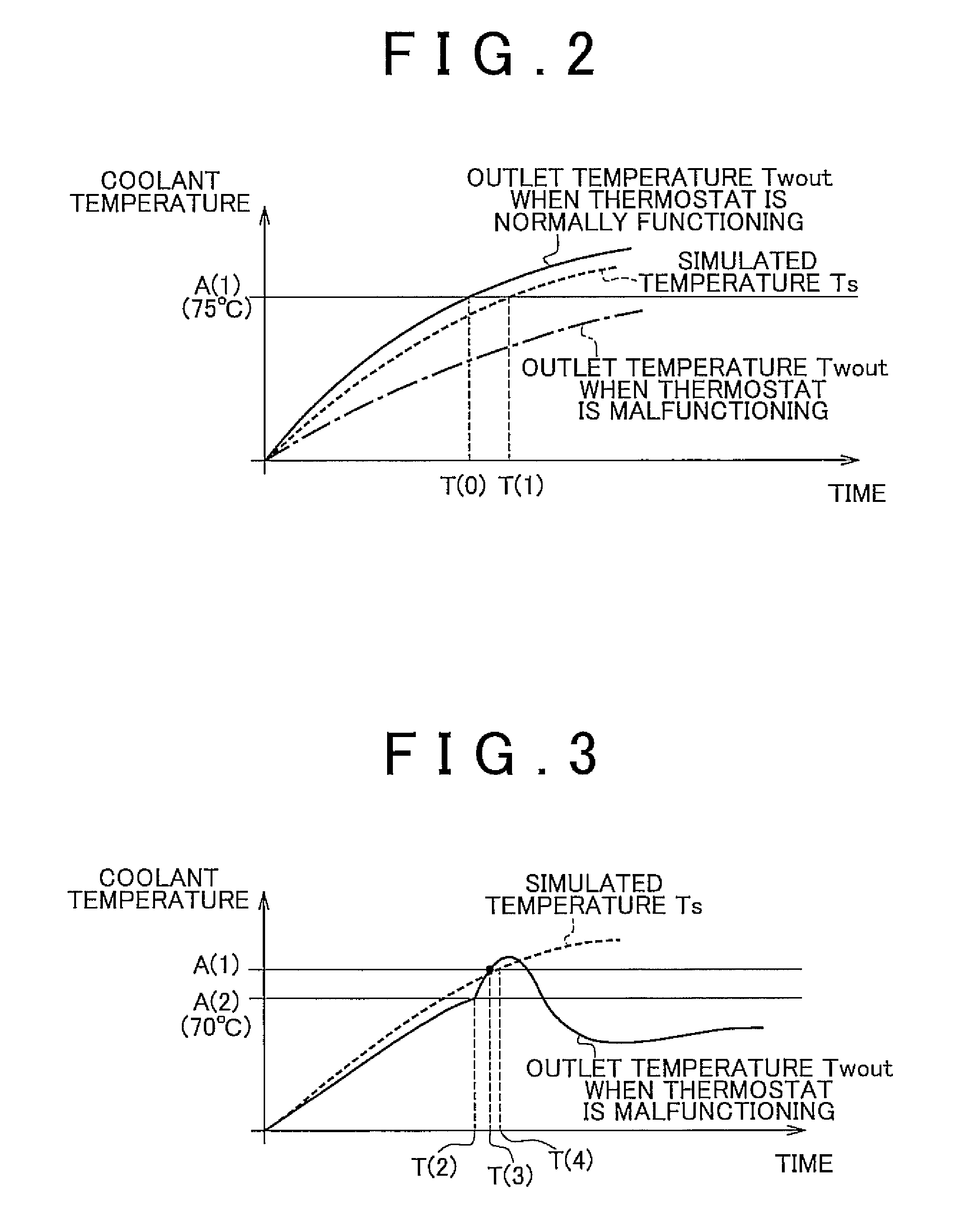
However, when the cooling medium is circulated in a medium passage included in a cooling apparatus using an electric pump, there is a possibility of making an erroneous determination as to whether a thermostat is malfunctioning, for the following reason.
Therefore, when the thermostat is malfunctioning, it may be erroneously determined that the thermostat is normally functioning.
Even in the malfunction determination apparatus described in the above-described publication, there is a possibility of making an erroneous determination relating to the thermostat due to a sharp change in an outlet temperature caused by the operation of the electric pump during warming-up, and this problem cannot be solved.

Method used


Image

  • Malfunction determination apparatus for cooling apparatus and malfunction determination method for cooling apparatus
  • Malfunction determination apparatus for cooling apparatus and malfunction determination method for cooling apparatus
  • Malfunction determination apparatus for cooling apparatus and malfunction determination method for cooling apparatus

Examples


Embodiment Construction

[0029]Hereinafter, an embodiment of the invention will be described with reference to the drawings. In the following description, the same or corresponding components are denoted by the same reference numerals, and have the same names and the same functions, and therefore, the detailed description thereof will not be repeated.

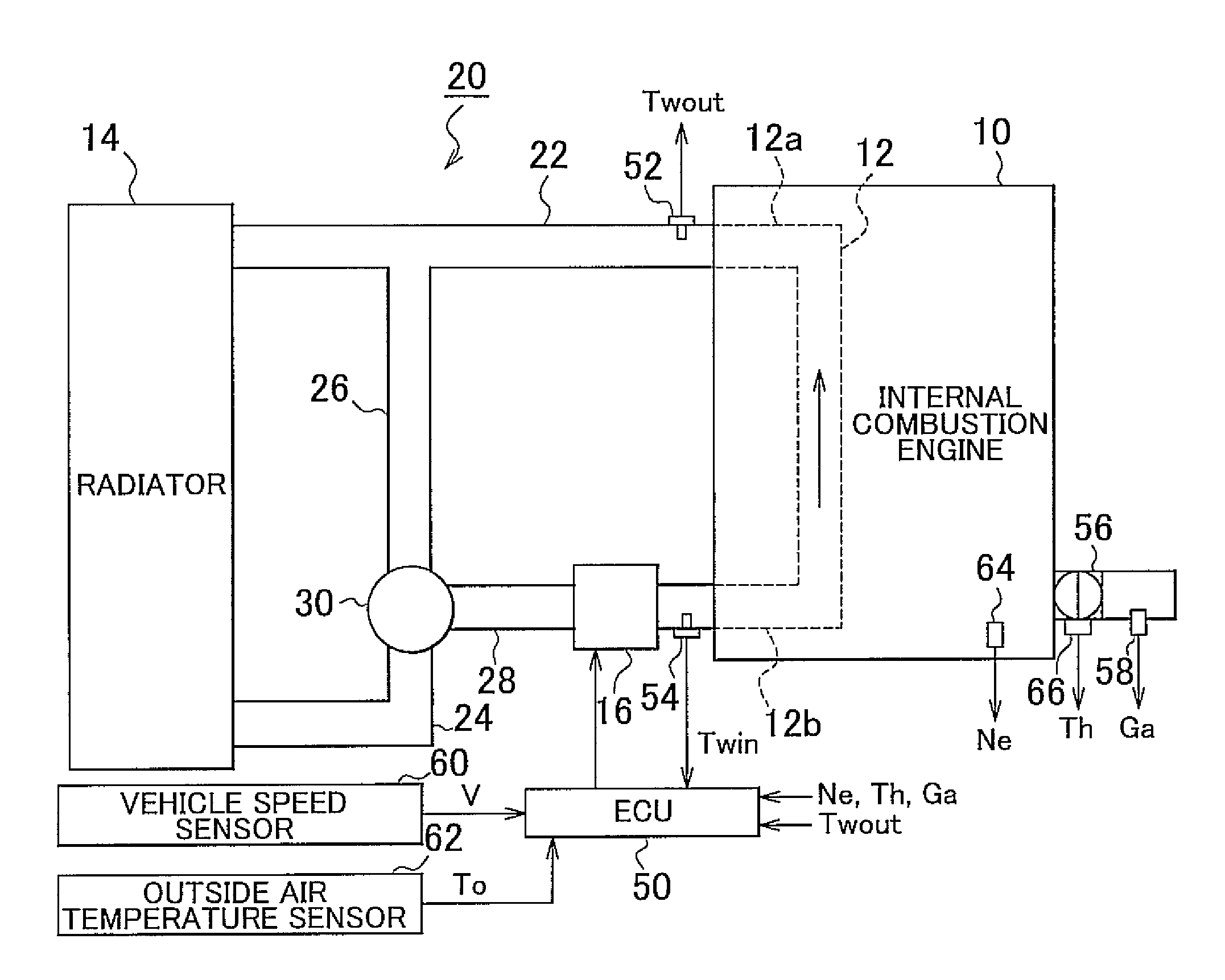
[0030]As shown in FIG. 1, a cooling apparatus according to the embodiment includes a water jacket 12 formed inside an internal combustion engine 10; a radiator 14; a circulation passage 20 for circulating coolant between the radiator 14 and the water jacket 12; a thermostat 30 provided in the circulation passage 20; an electric water pump 16 provided in the circulation passage 20; and an Electronic Control Unit (ECU) 50. A malfunction determination apparatus for the cooling apparatus according to the embodiment is implemented by the ECU 50. The cooling apparatus and the internal combustion engine in the embodiment are provided in a vehicle. The vehicle is not l...


PUM


Abstract

In a malfunction determination apparatus and a malfunction determination method for a cooling apparatus that cools an internal combustion engine by circulating a cooling medium that flows in a first passage that extends through an inside of the engine, using an electric pump, a first temperature of the cooling medium is detected at an inlet of the first passage, through which the cooling medium flows into the inside of the engine; a second temperature of the cooling medium is detected at an outlet of the first passage, through which the cooling medium flows out from the inside of the engine; and it is determined that the switching valve is able to normally select the second passage, if both of the first temperature and the second temperature reach a first threshold value when a temperature of the cooling medium increases due to start of the engine.

Description

CROSS REFERENCE TO RELATED APPLICATION[0001]This application claims priority to Japanese Patent Application No. 2009-266517 filed on Nov. 24, 2009, and which is incorporated herein by reference in its entirety including the specification, drawings and abstract.BACKGROUND OF THE INVENTION[0002]1. Field of the Invention[0003]The invention relates to a technology for determining whether a malfunction occurs in a cooling apparatus for an internal combustion engine, and particularly to a technology for accurately determining whether a thermostat is malfunctioning when a cooling medium, which flows through an inside of an internal combustion engine, is circulated by an electric pump.[0004]2. Description of the Related Art[0005]A cooling apparatus is provided for an internal combustion engine, and the cooling apparatus cools constituent components heated by heat generated by combustion. The cooling apparatus includes a thermostat. When the temperature of the cooling medium is lower than a ...

Claims


Application Information

Patent Timeline
Patent Type & Authority Patents(United States)
IPC IPC(8): G01M15/04
CPCF01P7/164G01M15/042F01P2025/13F01P2025/66F01P2031/00
Inventor SUGIMOTO, HITOKI
Owner TOYOTA JIDOSHA KK
Learn More