Method and apparatus for removal of pigs, deposits and other debris from pipelines and wellbores

a technology for removing pigs and other debris from pipelines and wellbores, which is applied in the direction of fluid removal, cleaning processes and equipment, and wellbore/well accessories, etc. it can solve the problems of limiting the forward progress of pigs, pigs can become stuck, and the wax or paraffin present in hydrocarbons can solidify, so as to achieve safe extension of the horizontal reach of coiled tubing, the effect of sufficient compression and extreme service flexibility

Active Publication Date: 2013-07-09
GIBSON IP LLC
View PDF17 Cites 9 Cited by
  • Summary
  • Abstract
  • Description
  • Claims
  • Application Information

AI Technical Summary

Benefits of technology

[0022]In the preferred embodiment, the present invention comprises a carrier assembly having a plurality of adjustable pre-programmed high pressure wash nozzles. Said carrier assembly can be advanced within a pipeline or well bore (including, without limitation, horizontal portions thereof) to a pre-determined location by pumping fluid into an annular space formed between said pipeline / wellbore and said carrier assembly. Said carrier assembly also provides a reverse circulation flow path to transfer fluid flow between the annulus and the tubing; that is, fluid pumped down the annulus can cross over through said carrier assembly, with such fluid being returned to the surface through the internal bore of the tubing. The circulation feature of said carrier assembly enables the use of tools requiring internal flow actuation including, without limitation, positive displacement motors, hip trippers, spinning wash tools, hydraulic fishing tools or the like.
[0023]In the preferred embodiment, the carrier assembly of the present invention maintains a pre-set, substantially constant pressure across said carrier assembly as fluid is pumped down a pipeline or well bore. The carrier assembly of the present invention also beneficially includes at least one sealing cup designed for extreme service and flexibility for wear. Said at least one sealing cup is further equipped with internal support to prevent said at least one cup from flipping or inverting when exposed to high pressures. In the preferred embodiment, said at least one sealing cup is beneficially spring loaded to bias said cup against the internal surface(s) of a pipeline or wellbore for longer cup wear, yet capable of sufficient compression to permit bi-directional service.
[0024]Further provided within said carrier assembly is an internal flow regulator and hydraulic control wash nozzles pre-set to maintain a pre-determined force that allows flow through said wash nozzles at pre-determined pressure(s). In the preferred embodiment, a spear assembly having a central bore is attached to said carrier assembly. Pumped fluids bypass said sealing cup(s), enter the flow-bore of said spear assembly, and return to the surface via the internal bore of the continuous tubing. The pre-set nozzle(s) in the carrier assembly help provide a motive force that propels the carrier assembly and attached coiled tubing down the pipeline as fluid is pumped at a pre-determined rate(s) and pressure(s).
[0025]All job site data can be logged in an on-site monitoring console, which can operate all parameters of a particular job. Said monitoring console can beneficially monitor and control loads, depth, pump pressure, running speeds and barrels pumped per minute.
[0026]In the preferred embodiment, the present invention provides an apparatus to safely extend the horizontal reach of coiled tubing in a controlled environment to clean out sections of pipelines and / or wellbores (including horizontal sections thereof) and to remove stuck pigs at great distances from a pipeline entry point. The present invention further provides a new method of generating a jetting action in a pipe line or wellbore using pre-set wash nozzles while advancing continuous tubing forward to a desired location of a stuck pig or other obstruction in said pipeline or wellbore. Additionally, the present invention provides a check valve system allowing the relief of compressed fluids as a stuck pig or other obstruction is speared or otherwise gripped. Once a pig or other obstruction is speared or otherwise gripped, the pig or other obstruction can then be retrieved from said pipeline using the continuous tubing.

Problems solved by technology

Frequently, this cooling can occur rapidly, causing wax or paraffin present in hydrocarbons to solidify.
As such paraffin and / or debris collects, it can build up and restrict the internal opening of the pipeline, eventually forming an obstruction that can limit forward progress of the pig.
Eventually, the pig can become stuck, such that it can not be moved by pressure from either direction, with the internal opening of the pipeline becoming fully obstructed.
While conventional devices known as injector heads can be used to grip the continuous tubing and mechanically force it into the pipeline from the surface, such tubing can become bent, kinked or “corkscrewed” during this process.
Furthermore, in the event that the continuous tubing enters a horizontal section of pipeline, the weight of the tubing can act against the internal surfaces of the pipeline, thereby creating frictional forces that impede the forward progress of the tubing through the pipeline.
As a result, conventional injector heads and other similar devices have proven to be less than satisfactory for purposes of conveying continuous tubing within pipelines.
However, the subject thruster device is not capable of simultaneously advancing in the pipeline and cleaning away obstructions in said pipeline.
Moreover, the thruster device will not allow pieces of debris to be circulated out of the pipeline behind the thruster device.

Method used


Image

  • Method and apparatus for removal of pigs, deposits and other debris from pipelines and wellbores
  • Method and apparatus for removal of pigs, deposits and other debris from pipelines and wellbores
  • Method and apparatus for removal of pigs, deposits and other debris from pipelines and wellbores

Examples


Embodiment Construction

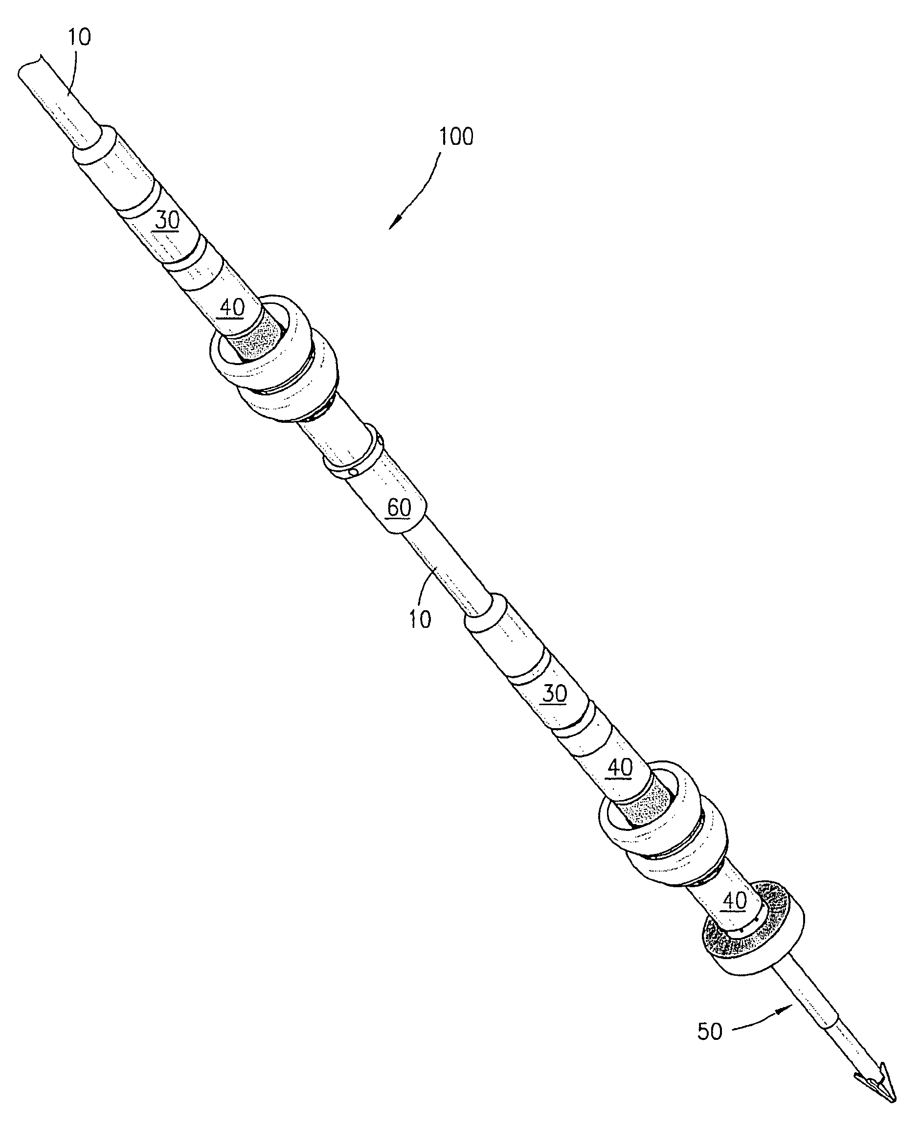
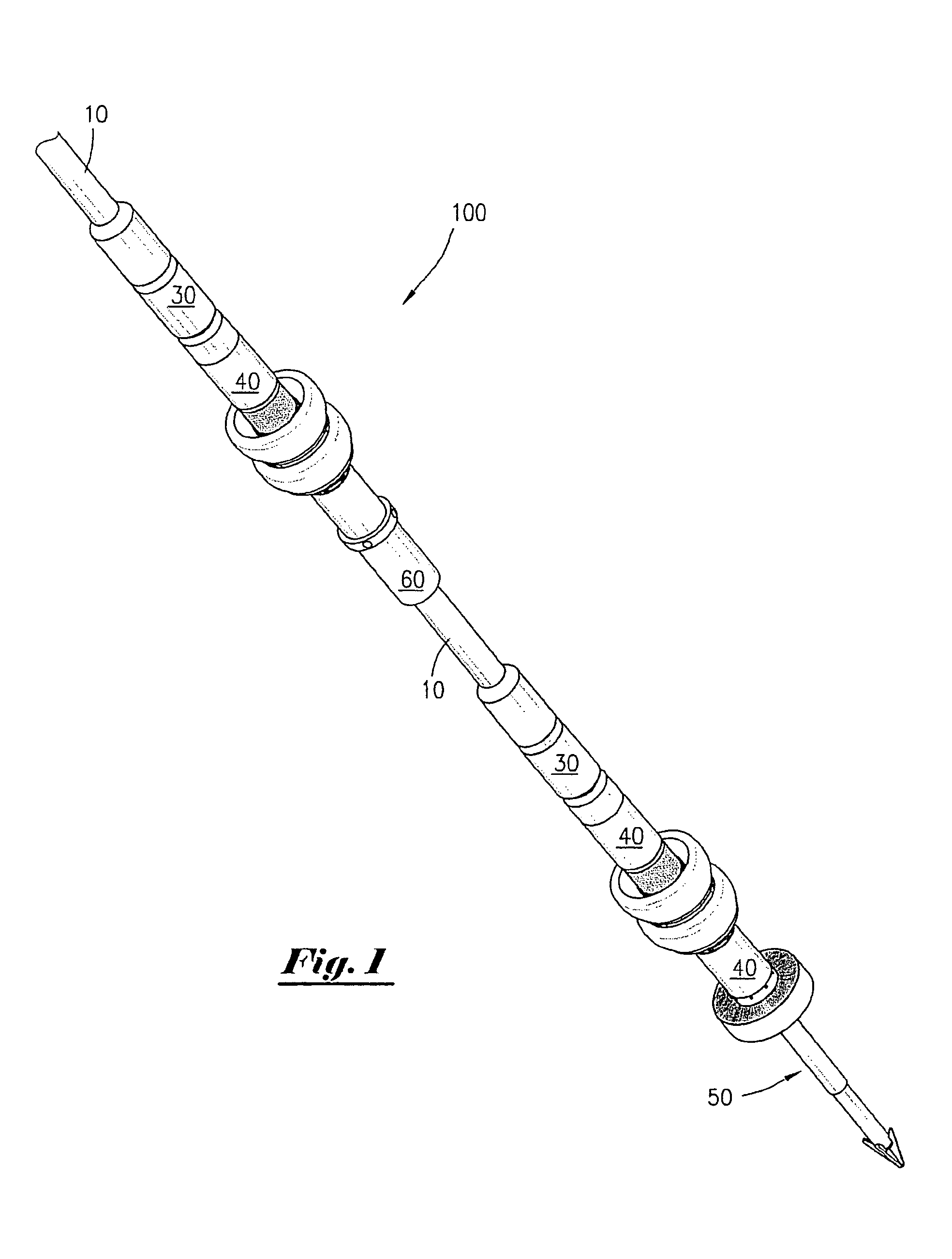
[0036]FIG. 1 depicts a perspective view of a plurality of carrier assemblies 100 of the present invention deployed via continuous tubing string 10, such as a length of continuous tubing associated with conventional coiled tubing units well known to those having skill in the art. Although the present invention is described herein primarily with regard to uses related to pipelines, it is to be observed that the present invention can also be used in connection with other applications or environments, such as within wellbores and the like. Further, although a plurality of carrier assemblies 100 are depicted in FIG. 1, such carrier assemblies 100 may be conveyed individually on a single length of continuous tubing, depending upon job parameters of a particular application.

[0037]Still referring to FIG. 1, carrier assemblies 100 are depicted as being optionally deployed in tandem with other devices well known to these having skill in the art. Such devices depicted in FIG. 1 include slip jo...


PUM


Abstract

A carrier assembly having at least one sealing cup, a fluid bypass and adjustable wash nozzles, as well as a spear assembly having a central through bore, are attached to the distal end of a length of continuous tubing and inserted in to the flow bore of a pipeline. Fluid is pumped through the annular space between the carrier assembly and the pipeline, providing motive force for advancing the carrier assembly within the pipeline. Fluid can bypass the carrier assembly, enter the central bore of the spear assembly, and return to the surface through the central bore of the continuous tubing. A stuck pig or other obstruction is speared, and thereafter retrieved from the pipeline on the continuous tubing.

Description

CROSS REFERENCES TO RELATED APPLICATION[0001]Priority of U.S. Provisional Patent Application Ser. No. 61 / 309,908 filed Mar. 3, 2010, both incorporated herein by reference, is hereby claimed.STATEMENTS AS TO THE RIGHTS TO THE INVENTION MADE UNDER FEDERALLY SPONSORED RESEARCH AND DEVELOPMENT[0002]None[0003]INVENTORS:[0004]James Bruce Crawford[0005]James Robert Crawford[0006]Joseph W. Elsbury, IIIBACKGROUND OF THE INVENTION[0007]1. Field of the Invention[0008]The present invention relates to a method and apparatus for the removal of obstructions, deposits and / or other debris from pipelines, wellbores and other confined areas. More particularly, the present invention relates to a method and apparatus for use of continuous tubing to remove obstructions restricting or completely preventing flow in pipelines or well bores including, without limitation, stuck pigs, hydrate plugs, scale, paraffin and / or other debris.[0009]2. Brief Description of the Prior Art[0010]As known deposits of oil an...

Claims


Application Information

Patent Timeline
Patent Type & Authority Patents(United States)
IPC IPC(8): E21B37/00
CPCB08B9/0557E21B37/00F16L55/46
Inventor CRAWFORD, JAMESCRAWFORD, JAMIE B.ELSBURY, III, JOSEPH W.
Owner GIBSON IP LLC
Why Eureka
Try Eureka