Traverse camshaft for fishing reel and reciprocal movement mechanism for fishing reel employing the traverse camshaft

a reciprocal movement mechanism and camshaft technology, applied in the direction of gearing, belt/chain/gearing, gearing, etc., can solve the problems of affecting the rotational operation feel of the reel, affecting the operation of the reel, and generating abnormal or undesirable noise, etc., to suppress the occurrence of abnormal noise, suppress the effect of unnecessary turning of the engaging member and reducing the operating feel of the user

Active Publication Date: 2013-07-09
SHIMANO INC
View PDF26 Cites 6 Cited by
  • Summary
  • Abstract
  • Description
  • Claims
  • Application Information

AI Technical Summary

Benefits of technology

[0011]One object of the present invention is to provide a traverse camshaft for a fishing reel that can suppress unnecessary turning of the engaging member and thereby suppress an occurrence of abnormal noise and degradation of the operating feel for a user.
[0014]In a reciprocal movement mechanism constructed using a traverse camshaft configured according this aspect of the invention, when the traverse camshaft rotates in a line reel-in direction, the engaging member moves along the cam groove so as to pass from the narrower first groove sections, through the intersecting portion, to the wider second groove sections. Thus, the engaging member repeatedly performs a movement in which it is restricted by the narrower first groove sections, enters the intersecting portion, and moves on to the wider second groove sections. As result, the engaging member is less likely to undergo unnecessary turning in the first groove sections and less likely to contact the intersecting portion. After the engaging member passes the intersecting portion, it does not readily contact the second groove sections because the second groove sections are wider.
[0015]Since the engaging member engages with the narrower first groove sections at a position rotationally downstream of the intersecting portion, i.e., at a position along the groove that the engaging member reaches just before reaching the intersecting portion when the traverse camshaft is rotated in the reel-in direction, unnecessary turning of the engaging member is suppressed before the engaging member enters the intersecting portion and the engaging member is less likely to contact the intersecting portion. Thus, the occurrence of abnormal noise and degradation of the operating feel caused by contact of the engaging member against the intersection portion are suppressed. Additionally, since the groove width widens when the engaging member passes the intersecting portion, the engaging member does not readily contact the second groove portion and the operating feel is less likely to decline. Consequently, unnecessary turning of the engaging member is suppressed and the occurrence of abnormal noise and degradation of the operating feel can also be suppressed.
[0018]In a traverse camshaft for a fishing reel according to still another aspect, the cam groove has third groove sections arranged rotationally upstream from the second groove sections, and the third groove sections are narrower than the second groove sections and wider than the first groove sections. With this aspect, third groove sections that are narrower than the second groove sections are formed rotationally upstream of the second groove sections between the second groove sections and the next upstream first groove sections. Consequently, the engaging member is restricted by the third groove sections that are narrower than the second groove sections as it moves from the second groove sections to the next upstream first groove sections and the engaging member can be guided more smoothly into the first groove sections. As a result, rocking of the engaging member can be suppressed to an even greater degree.

Problems solved by technology

However, since the engaging section of the engaging member is configured such that the middle portion is thicker in a thickness direction and both ends are thinner in the thickness direction, contact of the engaging member against the cam groove is limited to the middle portion.
Consequently, the engaging member can easily turn unnecessarily with respect to the cam groove and change the contact state between the engaging member and cam groove, possibly degrading the rotational operating feel of the reel due to a change in resistance.
Also, such turning of the engaging member at an intersecting portion of the cam groove can cause the engaging member to contact the intersecting portion and to generate an abnormal or undesirable noise.

Method used


Image

  • Traverse camshaft for fishing reel and reciprocal movement mechanism for fishing reel employing the traverse camshaft
  • Traverse camshaft for fishing reel and reciprocal movement mechanism for fishing reel employing the traverse camshaft
  • Traverse camshaft for fishing reel and reciprocal movement mechanism for fishing reel employing the traverse camshaft

Examples


first embodiment

General Description

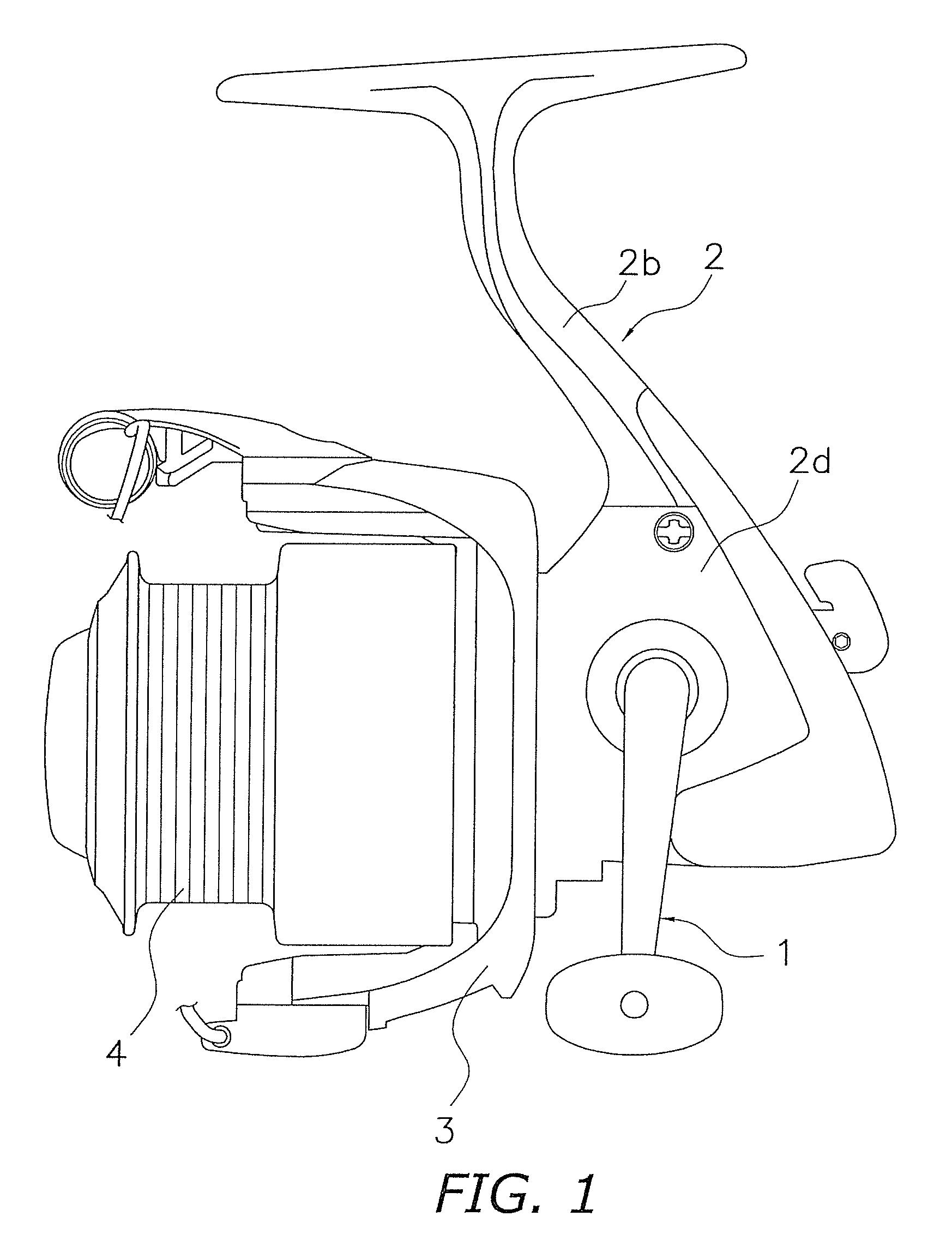
[0038]As shown in FIG. 1, a spinning reel according to a first embodiment has a reel unit 2, a handle assembly 1, a rotor 3, and a spool 4. The reel unit 2 is arranged such that it can be mounted to a fishing rod. The handle assembly 1 is mounted to the reel unit 2 such that it can rotate about a transverse axis (axis running left to right). The rotor 3 is arranged to rotate in coordination with rotation of the handle assembly 1 and to guide a fishing line to the spool 4. The rotor 3 is rotatably supported on a front portion of the reel unit 2 such that it can rotate about a longitudinal axis. The spool 4 is arranged in front of the rotor 3 such that can move reciprocally along a longitudinal axis and such that the fishing line guided by the rotor 3 can be wound onto an external circumferential surface of the spool 4.

Constituent Features of the Reel Unit

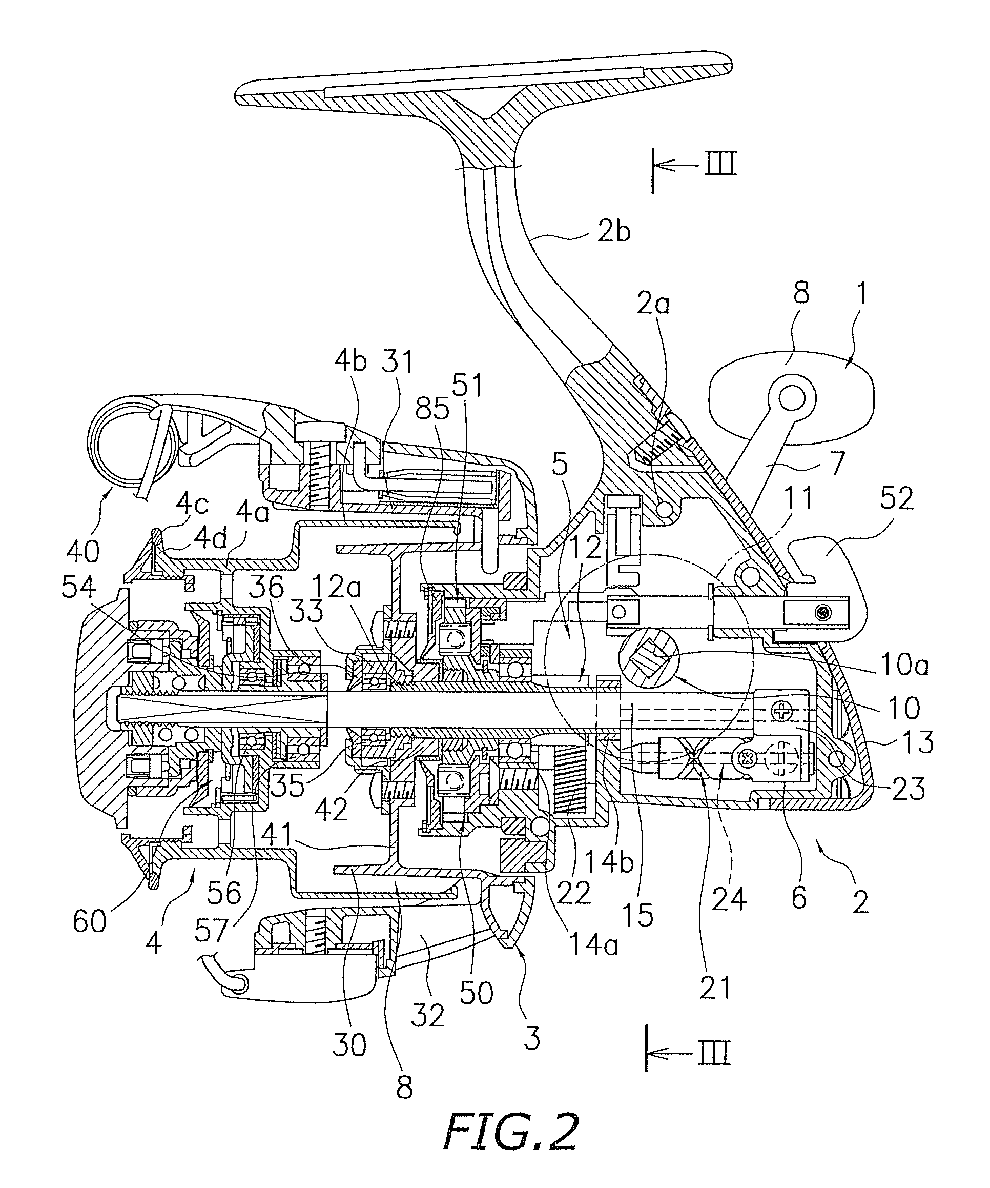
[0039]As shown in FIGS. 2 and 3, the reel unit 2 has a reel body 2a, a T-shaped rod mounting foot 2b, and a lid ...

second embodiment

[0085]FIG. 10 shows a dual-bearing reel in accordance a second embodiment. The dual bearing reel includes a reel unit 101, a handle assembly 102, a star drag 103 arranged on the reel unit 101 side of the handle assembly 102, and a spool 104. The handle assembly 102 is arranged on a side of the reel unit 101 and serves to rotate the spool 104. The handle assembly 102 has a plate-like arm part 102a and handle grips (not shown) mounted in a freely rotatable manner to both ends of the arm part 102a.

[0086]The reel unit 101 has a frame 105, first and second side covers 106 and 107 mounted on opposite sides of the frame 105, and a front cover 110 mounted on a front portion of the frame 105 such that it can be opened and closed.

[0087]The frame 105 has a pair of side plates 108 and 109 arranged facing each other with a prescribed space in-between and a plurality of connecting sections 111 arranged to connect the side plates 108 and 109 together. The spool 104 is arranged inside the frame 10...


PUM


Abstract

In a spinning reel, a traverse camshaft 21 is arranged to engage with an engaging member used to cause a bail arm and a spool to undergo a relative reciprocal movement. The traverse camshaft 21 has a shaft body 37 and a cam groove 38. The shaft body 37 is arranged to rotate in coordination with rotation of a handle assembly in at least a line reel-in direction. The cam groove 38 is formed in an external circumferential surface of the shaft body 37 and configured to engage with the engaging member. The cam groove 38 is also configured to intersect itself. The cam groove 38 has a first groove section 38b and a second groove section 38c on opposite sides of an intersecting portion 38a. The first groove section 38b and the second groove section 38c have different widths at the intersecting portion 38a.

Description

CROSS-REFERENCE TO RELATED APPLICATIONS[0001]This application claims priority to Japanese Patent Application No. 2009-014110 filed on Jan. 26, 2009. The entire disclosure of Japanese Patent Application No. 2009-014110 is hereby incorporated herein by reference.BACKGROUND OF THE INVENTION[0002]1. Field of the Invention[0003]The present invention relates to a traverse camshaft for a fishing reel and a reciprocal movement mechanism for a fishing reel. More specifically, the present invention relates to a traverse camshaft configured to engage with an engaging member that is used to cause a fishing line guide section and a spool of a fishing reel to undergo a relative reciprocal movement and to a reciprocal movement mechanism that employs such a traverse camshaft.[0004]2. Background Information[0005]Reciprocal movement mechanisms for fishing reels such as an oscillating mechanism of a spinning reel and a level wind mechanism of a dual-bearing reel use a traverse camshaft to cause a fish...

Claims


Application Information

Patent Timeline
Patent Type & Authority Patents(United States)
IPC IPC(8): A01K89/01
CPCA01K89/0114A01K89/015Y10T74/2101Y10T74/18312A01K89/0117A01K89/0192A01K89/01A01K89/027
Inventor OCHIAI, KOJIINOUE, TETSUO
Owner SHIMANO INC
Why Eureka
Try Eureka