
Resistor array and semiconductor device including the same

a resistor array and semiconductor technology, applied in semiconductor devices, diodes, electrical devices, etc., can solve the problems of unpredictability of resistance of passive resistors, instability of connection between passive resistors and metal wiring, etc., to prevent or inhibit dishing effect, improve semiconductor device performance, and improve semiconductor device productivity

Active Publication Date: 2013-07-09
SAMSUNG ELECTRONICS CO LTD
View PDF7 Cites 3 Cited by
  • Summary
  • Abstract
  • Description
  • Claims
  • Application Information

AI Technical Summary

Benefits of technology

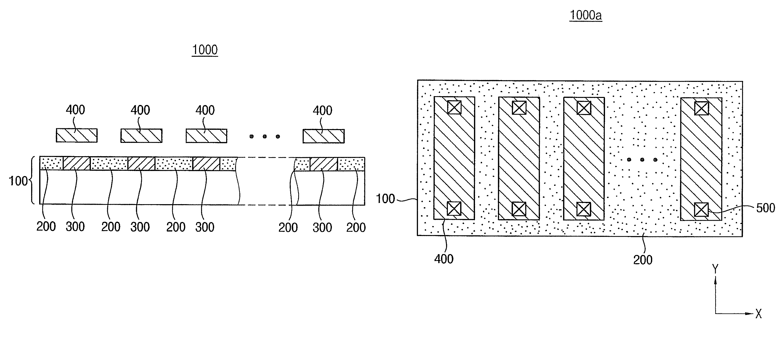
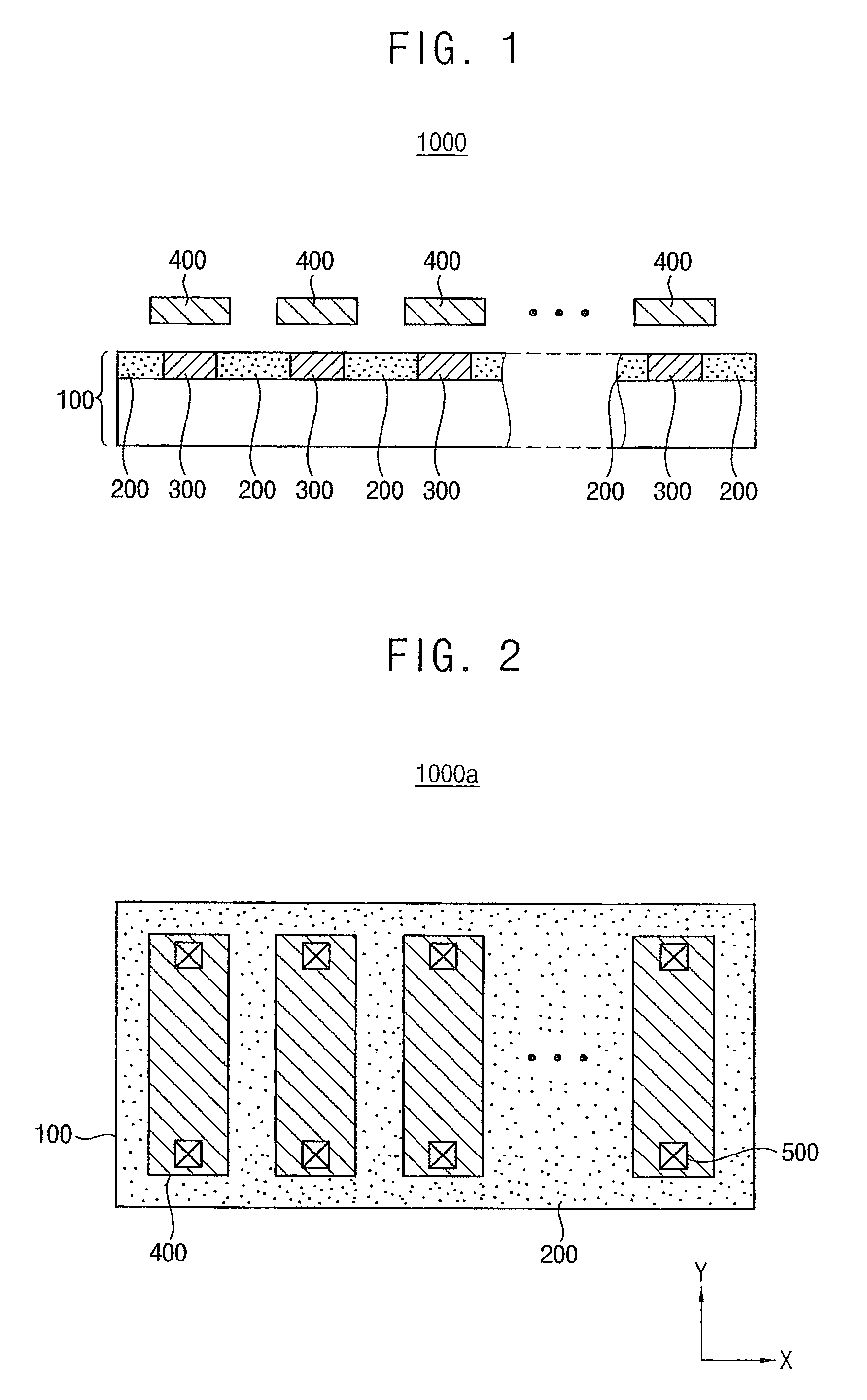
[0010]Some example embodiments provide a resistor array capable of preventing or reducing a dishing effect in a Chemical-Mechanical Polishing (CMP) process without an increase in the occupation area. Some example embodiments also provide a semiconductor device including the resistor array.
[0031]The resistor array and the semiconductor device according to example embodiments may prevent or inhibit a dishing effect in a CMP process without an increase of occupation area. Therefore, productivity of the semiconductor device may be increased, and the performance of the semiconductor device may be enhanced.

Problems solved by technology

This dishing effect may cause instability of connection between the passive resistor and metal wiring.
In addition, the resistance of the passive resistor may be unpredictably varied due to the dishing effect.

Method used


Image

  • Resistor array and semiconductor device including the same
  • Resistor array and semiconductor device including the same
  • Resistor array and semiconductor device including the same

Examples


Embodiment Construction

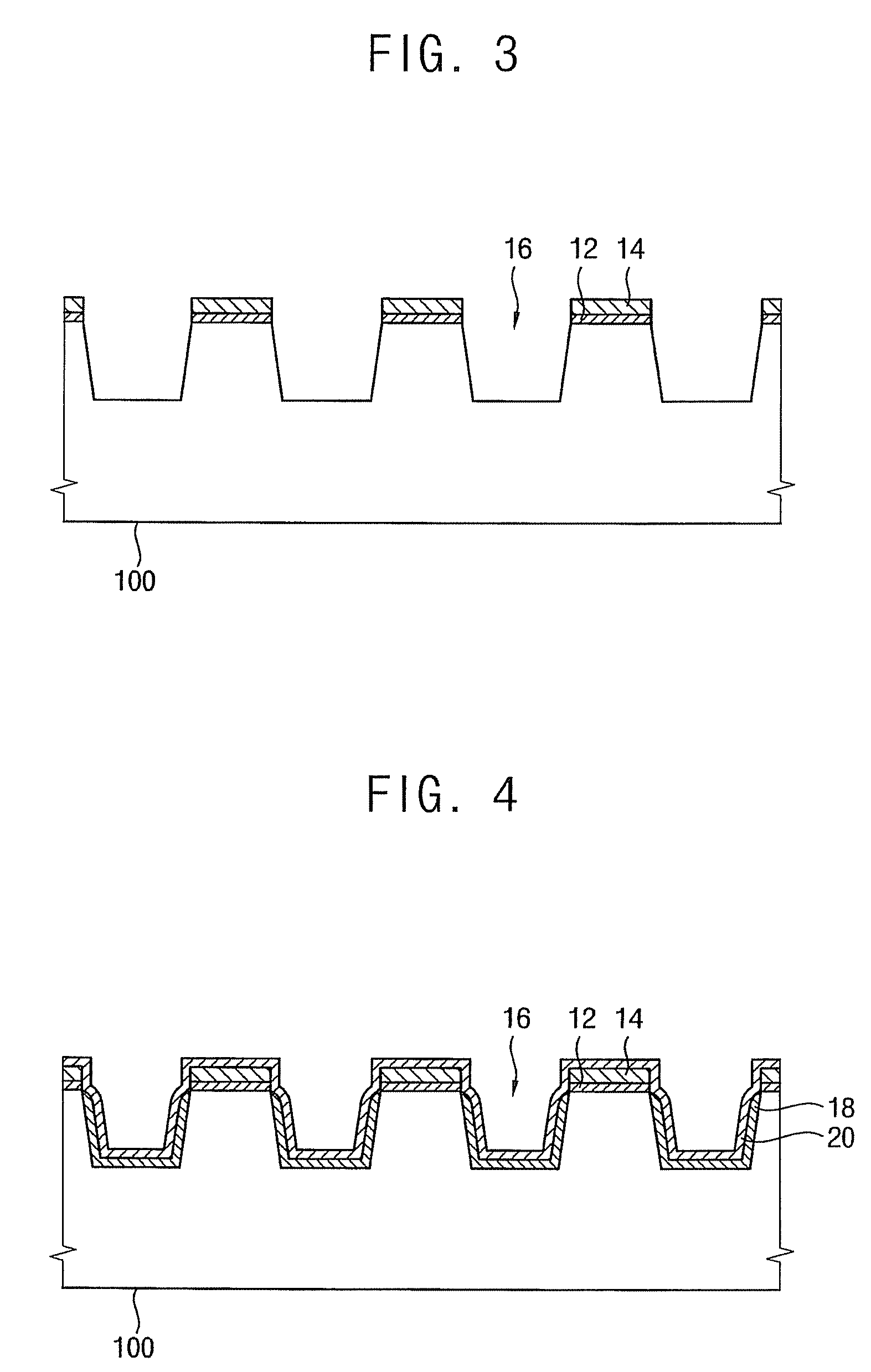
[0042]Various example embodiments will be described more fully hereinafter with reference to the accompanying drawings, in which some example embodiments are shown. The present inventive concept may, however, be embodied in many different forms and should not be construed as limited to the example embodiments set forth herein. Rather, these example embodiments are provided so that this disclosure will be thorough and complete, and will fully convey the scope of the present inventive concept to those skilled in the art. In the drawings, the sizes and relative sizes of layers and regions may be exaggerated for clarity. Like numerals refer to like elements throughout.

[0043]It will be understood that, although the terms first, second, third etc. may be used herein to describe various elements, these elements should not be limited by these terms. These terms are used to distinguish one element from another. Thus, a first element discussed below could be termed a second element without de...


PUM


Abstract

A resistor array includes a semiconductor substrate, a plurality of isolation regions, a plurality of dummy active regions and a plurality of unit resistors. The plurality of isolation regions are formed in the semiconductor substrate. The plurality of dummy active regions are formed in the semiconductor substrate between the plurality of isolation regions. The plurality of unit resistors are formed on the plurality of dummy active regions.

Description

CROSS-REFERENCE TO RELATED APPLICATION(S)[0001]This application claims priority under 35 USC §119 to Korean Patent Application No. 10-2010-0086249, filed on Sep. 3, 2010, in the Korean Intellectual Property Office (KIPO), the contents of which are incorporated herein in its entirety by reference.BACKGROUND[0002]1. Technical Field[0003]Example embodiments relate generally to semiconductor devices. For example, example embodiments of the inventive concepts relate to a resistor array formed using a semiconductor substrate and a semiconductor device including the same.[0004]2. Description of the Related Art[0005]Resistors used in semiconductor devices may be classified into active resistors and passive resistors. The active resistors include a resistive portion formed in a semiconductor substrate. The passive resistors correspond to separate resistive structures formed on the semiconductor substrate.[0006]The active resistors may include diffusion regions for resistive materials. Impuri...

Claims


Application Information

Patent Timeline
Patent Type & Authority Patents(United States)
IPC IPC(8): H01L27/105
CPCH01L27/0802H01L27/0629H01L27/0738
Inventor CHO, YOUNG-JIN
Owner SAMSUNG ELECTRONICS CO LTD
Learn More