Variable voltage DC-DC converter

a dc-dc converter and variable voltage technology, applied in the direction of dc-dc conversion, power conversion systems, instruments, etc., can solve the problems of reduced response speed in changing the output voltage of dc-dc converters, increase in current consumption, and substantial increase in power consumption

Inactive Publication Date: 2013-07-09
RICOH ELECTRONIC DEVICES CO LTD
View PDF28 Cites 6 Cited by
  • Summary
  • Abstract
  • Description
  • Claims
  • Application Information

AI Technical Summary

Benefits of technology

[0031]According to one aspect of the present invention, there is provided a DC-DC converter whose output voltage can quickly follow a change in a reference voltage.

Problems solved by technology

However, higher clock frequencies cause the problem of an increase in current consumption proportional to the increase in clock frequency.
This results in a substantial increase in power consumption.
However, if the same clock signal is used for causing the d / a converter to operate and for switching the DC-DC converter, this results in the problem of reduction in response speed in changing the output voltage of the DC-DC converter.
Also in the case of reducing the reference voltage Vref, there is a problem in that the change of the output voltage Vo is always delayed by one clock cycle as indicated by P5 and P6 of the clock signal CLK in FIG. 3.

Method used


Image

  • Variable voltage DC-DC converter
  • Variable voltage DC-DC converter
  • Variable voltage DC-DC converter

Examples


Embodiment Construction

[0039]A description is given below, with reference to the accompanying drawings, of an embodiment of the present invention.

[0040]FIG. 4 is a circuit diagram illustrating a DC-DC converter according to the embodiment of the present invention.

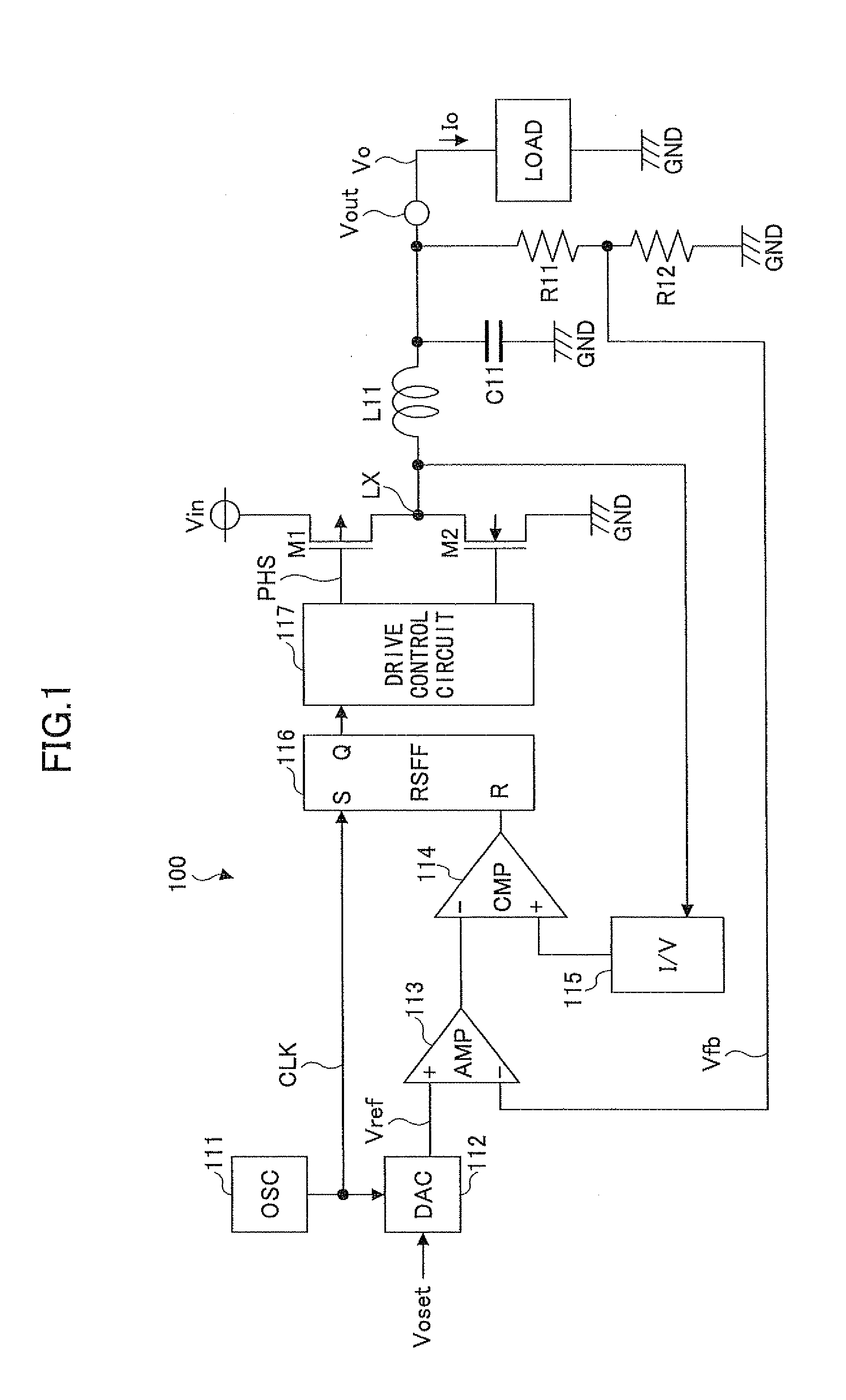
[0041]Referring to FIG. 4, a DC-DC converter 10 of this embodiment, which is a current-mode controlled DC-DC converter, includes an oscillator circuit (OSC) 11, a d / a converter (DAC) 12, an error amplifier circuit (AMP) 13, a delay circuit 18, a pulse-width modulation (PWM) comparator (CMP) 14, an inductor current detector circuit (I / V) 15, an R-S flip-flop circuit (RSFF) 16, a drive control circuit 17, a switching transistor M1 formed of a PMOSFET, a synchronous rectification transistor M2 formed of an NMOSFET, an inductor L1, a capacitor C1, a resistor R1, and a resistor R2.

[0042]The delay circuit 18 is connected between the oscillator circuit 11 and the SET input S of the R-S flip-flop circuit 16.

[0043]The oscillator circuit 11 outputs a first...


PUM


Abstract

A DC-DC converter configured to vary an output voltage includes an oscillator circuit configured to output a first clock signal; a digital-to-analog converter controlled based on the first clock signal input thereto and configured to output a voltage according to a voltage setting signal; a delay circuit configured to output a second clock signal delayed by a predetermined delay time with respect to the first clock signal input thereto; an error amplifier circuit having the output voltage of the digital-to-analog converter input thereto as a reference voltage; a pulse width modulation comparator provided with an output of the error amplifier circuit and a voltage into which a current flowing through an inductor is converted; and a control part configured to control a switching transistor of the DC-DC converter based on the second clock signal output by the delay circuit and an output of the pulse width modulation comparator.

Description

TECHNICAL FIELD[0001]A certain aspect of one or more embodiments discussed herein is related to DC-DC converters capable of varying voltage, such as a DC-DC converter using the output voltage of a digital-to-analog (d / a) converter for a reference voltage.BACKGROUND ART[0002]In these years, it has been desired to save energy in terms of environmental measures as well. In apparatuses using batteries, such as cellular phones and digital cameras, it has become increasingly important to reduce power consumed inside the apparatus in terms of a longer battery service life as well. Therefore, non-isolated DC-DC converters using an inductor, which are highly efficient and also reducible in size, are often used as power supply circuits.[0003]Further, apparatuses have become more sophisticated, so that, for example, video has been recorded and reproduced more frequently than still images. As a result, CPUs used in apparatuses have become higher in performance to operate at higher clock frequen...

Claims


Application Information

Patent Timeline
Patent Type & Authority Patents(United States)
IPC IPC(8): G05F1/40
CPCH02M3/158H02M2001/0025H02M1/0025
Inventor NODA, IPPEI
Owner RICOH ELECTRONIC DEVICES CO LTD
Why Eureka
Try Eureka