Hydrogen storage apparatus with heat-dissipating structure

a technology of hydrogen storage and heat dissipation structure, which is applied in the direction of packaging goods, container discharging methods, separation processes, etc., can solve the problems of limited hydrogen absorption capacity of metal alloys, high cost of these two hydrogen storage apparatuses, and large energy consumption for liquefying or compressing hydrogen, so as to achieve the effect of increasing the thermal conduction efficiency

Inactive Publication Date: 2015-03-10
NAT CENT UNIV
View PDF17 Cites 2 Cited by
  • Summary
  • Abstract
  • Description
  • Claims
  • Application Information

AI Technical Summary

Benefits of technology

[0009]In view of the foregoing subject, an objective of the present invention is to provide a hydrogen storage apparatus that can effectively increase the thermal conduction efficiency during absorbing or releasing hydrogen.
[0023]As mentioned above, the hydrogen storage unit of the hydrogen storage apparatus of the invention is made of the material with high thermal conductivity, and the heat-dissipating partitions of the hydrogen storage unit can evenly divide the inner space of the housing. Accordingly, the heat generated in the hydrogen absorbing and releasing procedures can be conducted or removed from inside to outside or from outside to inside, thereby improving the thermal conduction efficiency of the hydrogen storage apparatus. In addition, since the heat-dissipating partition is configured with the second holes, hydrogen contained in the compartments of the hydrogen storage unit can rapidly follow in lateral so as to homogenously distribute in the hydrogen storage materials. This configuration can improve the hydrogen absorbing and releasing rates. Moreover, the grooves are configured with first holes and form radial hydrogen channels between the hydrogen storage unit and the housing, so that the hydrogen contained in the hydrogen storage unit can enter the radial hydrogen channels through the first holes and then flow longitudinally. Thus, the distribution of the hydrogen in the entire canister will be more uniform, and the poor gas fluidness can be prevented.

Problems solved by technology

However, when the hydrogen is stored either in a low-temperature liquid state or a high-pressure gaseous state, a lot of energy has to be consumed to liquefy or compress the hydrogen.
Thus, the costs for these two hydrogen storage apparatuses are very high.
However, the hydrogen absorption capacity of the metal alloy is limited.
However, this disclosed structure is very complicated and difficult in fabrication.

Method used


Image

  • Hydrogen storage apparatus with heat-dissipating structure
  • Hydrogen storage apparatus with heat-dissipating structure
  • Hydrogen storage apparatus with heat-dissipating structure

Examples


Embodiment Construction

[0034]The present invention will be apparent from the following detailed description, which proceeds with reference to the accompanying drawings, wherein the same references relate to the same elements.

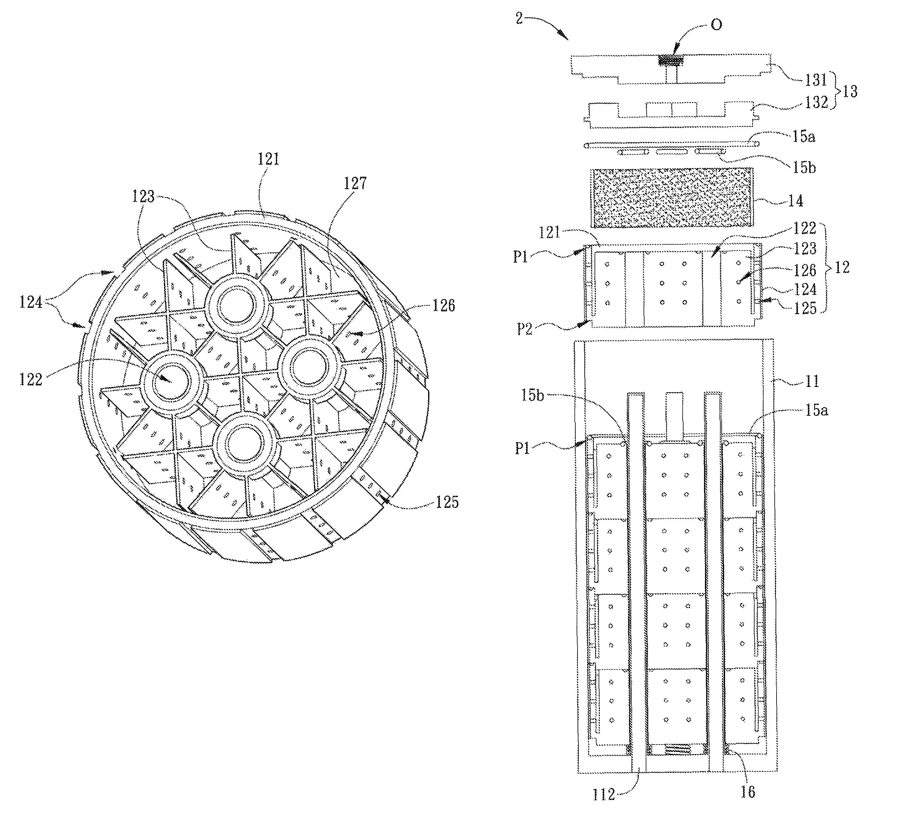
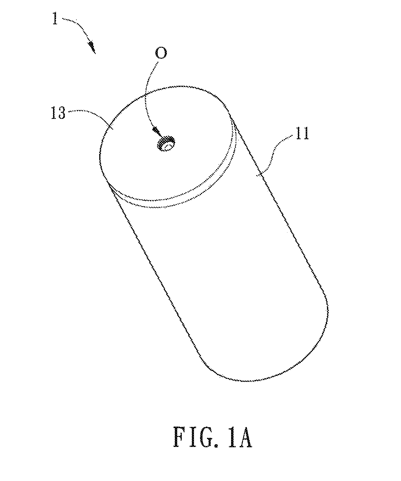
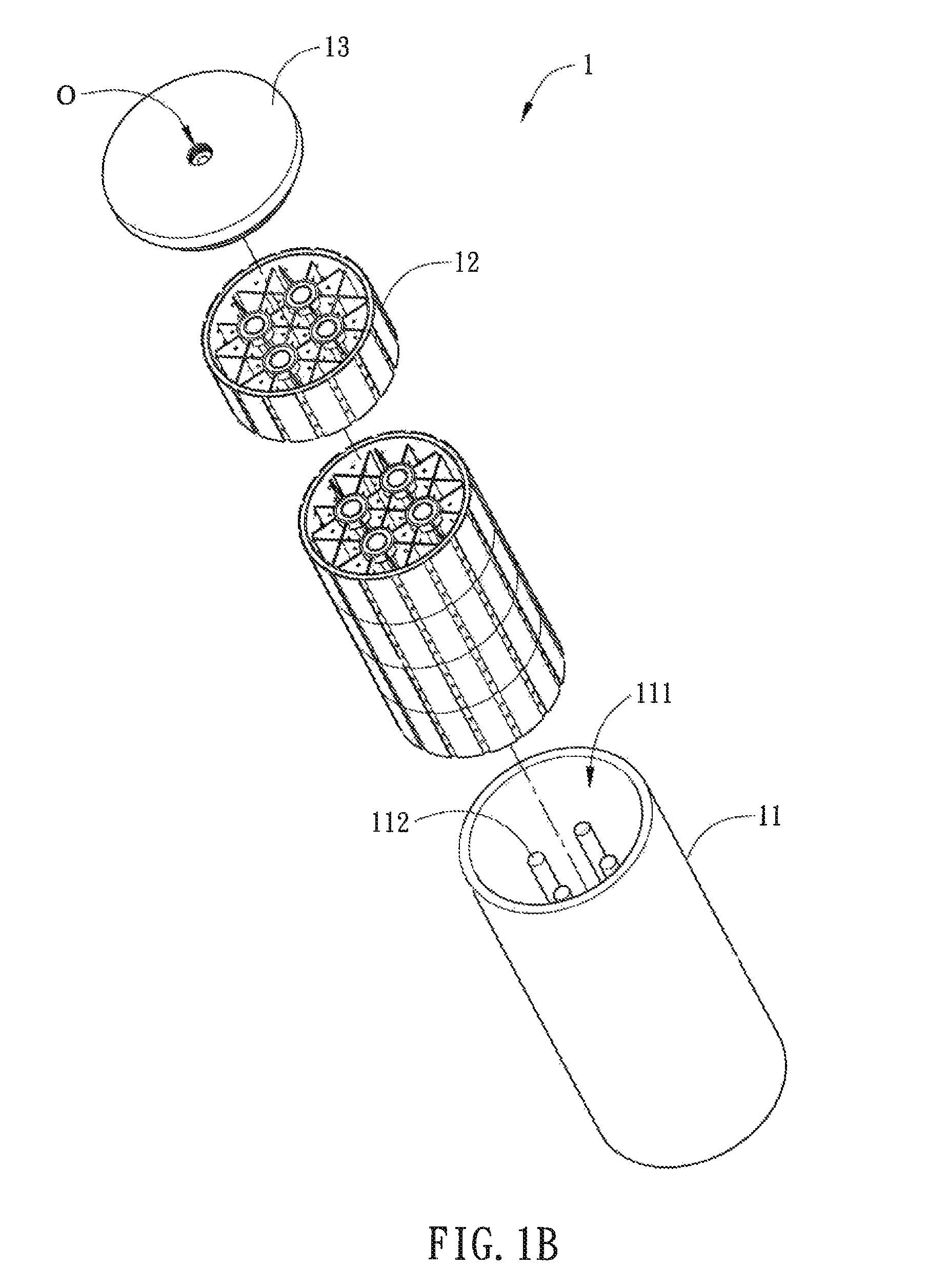
[0035]FIG. 1A is a schematic diagram of a hydrogen storage apparatus 1 according to an embodiment of the invention, and FIG. 1B is an exploded view of the hydrogen storage apparatus 1 of FIG. 1A. Referring to FIGS. 1A and 1B, the hydrogen storage apparatus 1 includes a canister 11 and at least one hydrogen storage unit 12. The cross-section of the canister 11 is, for example but not limited to, a circle, an ellipsoid, a square, a pentagon, a hexagon, or other polygons. The center of the canister 11 is configured with a space 111. In this embodiment, the canister 11 is a hollow rod, and the cross-section thereof is a circle. Five hydrogen storage units 12 are provided, and the size of the canister 11 is large enough to accommodate all of the five hydrogen storage units 12. Of course, t...


PUM

PropertyMeasurementUnit
diameteraaaaaaaaaa
diameteraaaaaaaaaa
diametersaaaaaaaaaa

Abstract

A hydrogen storage apparatus includes a canister and at least one hydrogen storage unit. The canister has at least a hollow rod. The hydrogen storage unit is disposed in the canister. The hydrogen storage unit includes a housing, a heat-dissipating channel and a plurality of heat-dissipating partitions. The periphery of the housing is configured with a plurality of grooves, and each groove has a plurality of first holes. The heat-dissipating channel is located within the housing. Each heat-dissipating partition has a plurality of second holes and connects to the housing and heat-dissipating channel. The heat-dissipating partitions divide the space inside the housing. The first holes and the second holes connect to the inner space of the housing.

Description

CROSS REFERENCE TO RELATED APPLICATIONS[0001]This Non-provisional application claims priority under 35 U.S.C. §119(a) on Patent Application No(s). 101132492 filed in Taiwan, Republic of China on Sep. 6, 2012, the entire contents of which are hereby incorporated by reference.BACKGROUND OF THE INVENTION[0002]1. Field of Invention[0003]The present invention relates to a gas storage apparatus and, in particular, to a hydrogen storage apparatus.[0004]2. Related Art[0005]Recently, hydrogen has been widely applied to the industrial manufacturing processes, and the specifications in the fields of manufacturing, storage, transportation and application thereof have been gradually specified perfectly. The current hydrogen storage technology mainly includes the liquefied hydrogen storage, the high-pressure hydrogen storage, the metal hydride hydrogen storage, the alloy hydrogen storage, and the like. However, when the hydrogen is stored either in a low-temperature liquid state or a high-pressur...

Claims


Application Information

Patent Timeline
Patent Type & Authority Patents(United States)
IPC IPC(8): B65D85/00F17C1/00B01D53/053F17C1/12
CPCF17C1/12Y02E60/321F17C11/005Y02E60/32Y02P90/45F17C11/00
Inventor CHUNG, CHIH-ANGHUANG, TENG-YI
Owner NAT CENT UNIV
Why Eureka
Try Eureka