

Current drive of tripolar magneto-rheological damper
A magnetorheological damper, current driver technology, applied in the direction of converting DC power input to DC power output, instruments, shock absorbers, etc., can solve the problems of voltage and current fluctuations of bipolar current drivers, and achieve faster current response. Speed, the effect of reducing the impact of the current
- Summary
- Abstract
- Description
- Claims
- Application Information
AI Technical Summary
Problems solved by technology
Method used
Image

Examples
Embodiment 1
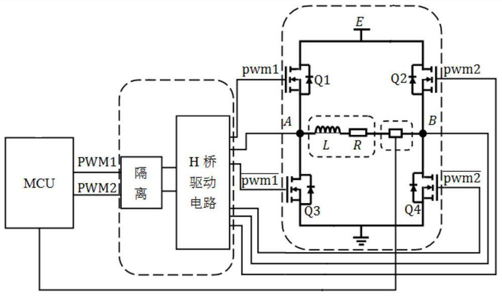
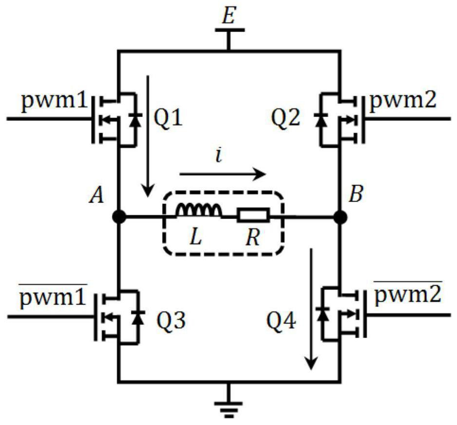
[0044] see Figure 1 to Figure 7 A current driver for a tripolar magneto-rheological damper comprises a current feedback circuit, a control circuit, a MOS tube drive circuit, a full bridge circuit and a current feedback circuit.
[0045] The current feedback circuit monitors the current in the magnetorheological damper coil, and sends the monitored current to the control circuit.
[0046] The current feedback circuit is a Hall-type current sensor connected in series with the magneto-rheological damper coil.
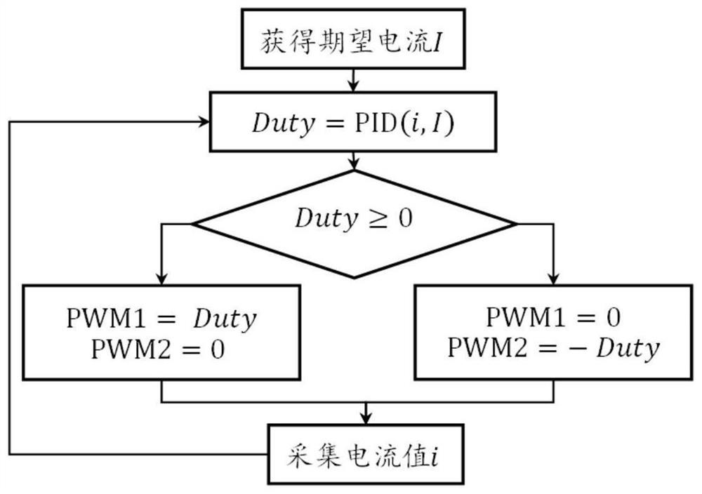
[0047] The control circuit receives the external expected current I(k) and the monitoring current i(k) sent by the current feedback circuit, and determines the duty cycle of the two PWM signals according to the expected current I(k) and the monitoring current i(k) .
[0048] The method for the control circuit to determine the duty cycle of the two PWM signals is: the control circuit calculates the generalized duty cycle Duty(k) according to the PID control algorithm. g...
Embodiment 2
[0076] see Figure 1 to Figure 7 A current driver for a tripolar magneto-rheological damper comprises a current feedback circuit, a control circuit, a MOS tube drive circuit, a full bridge circuit and a current feedback circuit.
[0077] The current feedback circuit monitors the current in the magnetorheological damper coil, and sends the monitored current to the control circuit.
[0078] The current feedback circuit is a sampling resistor connected in series with the magnetorheological damper coil.
[0079] The control circuit receives the external expected current I(k) and the monitoring current i(k) sent by the current feedback circuit, and determines the duty cycle of the two PWM signals according to the expected current I(k) and the monitoring current i(k) .
[0080] The method for the control circuit to determine the duty cycle of the two PWM signals is: the control circuit calculates the generalized duty cycle Duty(k).
[0081] When the generalized duty ratio Duty(k)...
Embodiment 3
[0099] see Figure 1 to Figure 7 A current driver for a tripolar magneto-rheological damper comprises a current feedback circuit, a control circuit, a MOS tube drive circuit, a full bridge circuit and a current feedback circuit. Including current feedback circuit, control circuit, MOS tube drive circuit, full bridge circuit and current feedback circuit;
[0100] The current feedback circuit monitors the current in the magnetorheological damper coil, and sends the monitored current to the control circuit;
[0101] The control circuit receives the external expected current I(k) and the monitoring current i(k) sent by the current feedback circuit, and determines the duty cycle of the two PWM signals according to the expected current I(k) and the monitoring current i(k) ;
[0102] The control circuit generates two PWM signals and sends them to the MOS transistor drive circuit;
[0103] After the MOS tube drive circuit receives two PWM signals, it generates a switching tube cont...
PUM
 Abstract
Description
Claims
Application Information