Synchronizing signal processing circuit

a signal processing circuit and signal processing technology, applied in the field of can solve the problems of inability to quickly synchronize the output with the input of conventional synchronizing signal processing circuits, and the inability to reproduce synchronizing signals with abrupt phase shifts, etc., to achieve stable horizontal sync signals

Inactive Publication Date: 2005-09-06
MITSUBISHI ELECTRIC CORP
View PDF4 Cites 2 Cited by
  • Summary
  • Abstract
  • Description
  • Claims
  • Application Information

AI Technical Summary

Benefits of technology

[0014]With the above-described horizontal sync signal processing circuit, it is possible to obtain stable horizontal sync signals by removing false synchronizing pulses and compensating for missing synchronizing pulses. However, the above-described conventional synchronizing signal processing circuit is used on the premise that incoming synchronizing signals have a period (or multiples of the period) that is fundamentally constant and have continuity in phase if false synchronizing pulses are included therein or there is a momentary loss of a pulse therein, and that the phase of the incoming synchronizing signals does not shift abruptly.
[0021]The present invention has been made to solve the above-described problems with an object of providing a synchronizing signal processing circuit capable of not only removing false synchronizing pulses included in incoming synchronizing signals and compensating for missing signals, but also causing its output to follow its input quickly after a phase of the incoming synchronizing signals has shifted abruptly.

Problems solved by technology

However, abrupt phase shift can occur to reproduced synchronizing signals during video reproduction by a VCR for example.
The above-described conventional synchronizing signal processing circuit is not able to synchronize its output with its input quickly when such abrupt phase shift has occurred.

Method used


Image

  • Synchronizing signal processing circuit
  • Synchronizing signal processing circuit
  • Synchronizing signal processing circuit

Examples


Embodiment Construction

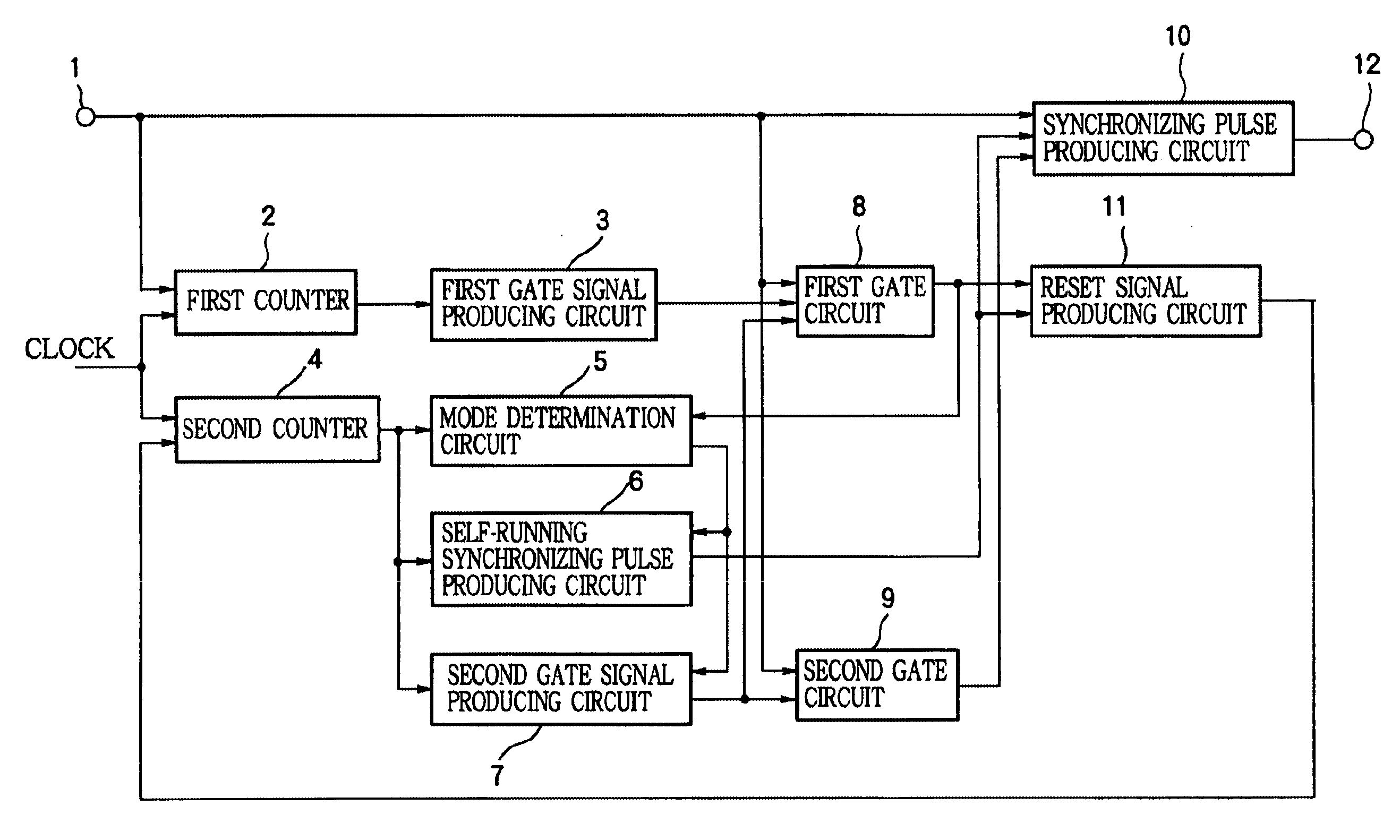
[0064]FIG. 1 is a block diagram showing a structure of a synchronizing signal processing circuit of a first example according to invention. In FIG. 1, 1 denotes an input terminal for receiving synchronizing signals, 2 denotes a first counter counting a clock of a predetermined frequency and being reset to 0 each time a synchronizing signal enters through the input terminal 1,3 denotes a first gate signal producing circuit for producing a first gate signal which indicates an open state after the count value of the first counter 2 reaches a predetermined first value and indicates a closed state after the first counter 2 is reset or after the count value of the first counter 2 reaches a second value larger than the first value, 4 denotes a second counter counting the clock and being reset to 0 by a reset signal produced by an after-described reset signal producing circuit 11, 5 denotes a mode determination circuit which sets a self-running mode flag to be supplied to an after-described...


PUM


Abstract

A synchronizing signal processing circuit for use in a video apparatus such as a display apparatus and an information recording / reproducing is disclosed. The synchronizing signal processing circuit is capable of not only removing false synchronizing pulses included in incoming synchronizing signals and compensating for missing signals, but also causing its output to follow its input quickly after a phase of the incoming synchronizing signals has shifted abruptly.

Description

FIELD OF THE INVENTION[0001]The present invention relates to a synchronizing signal processing circuit for use in a video apparatus such as a display apparatus and an information recording / reproducing apparatus, particularly relates to a synchronizing signal processing circuit capable of outputting stable synchronizing signals having a small period variation by removing false synchronizing signals from incoming synchronizing signals and by compensating for missing synchronizing signals.BACKGROUND OF THE INVENTION[0002]Video apparatuses need stable synchronizing signals having a small period variation to display or record images. However, when radio waves received in an antenna are weak or when channel changing is made, a period of synchronizing signals can be disturbed temporarily. In addition, since false synchronizing signals such as equalizing pulses and cut-in pulses having frequencies which are integral multiples of the frequency of horizontal sync signals are included in each ...

Claims


Application Information

Patent Timeline
Patent Type & Authority Patents(United States)
IPC IPC(8): H03L7/00H04N5/12H04L7/033H04N5/08H04N5/067H04N5/073H04N9/64H04N5/46H04N5/06G09G5/00G09G5/12H04N5/04
CPCH03L7/00H04L7/0331H04N5/073H04N5/08H04N5/126H04N5/46H04N9/641H04N21/4302
Inventor SUZUKI, YOSHITOMINAMI, KOUJI
Owner MITSUBISHI ELECTRIC CORP
Why Eureka
Try Eureka