Stroboscopic animation system

a technology of stroboscopic light and animation system, which is applied in the field of stroboscopic light, can solve the problems of easy damage, prone to malfunction, and high cost of reproduction, and achieve the effect of improving safety and convenience of stroboscopic light and effective animation

Active Publication Date: 2013-07-09
SEDER RUFUS BUTLER
View PDF12 Cites 8 Cited by
  • Summary
  • Abstract
  • Description
  • Claims
  • Application Information

AI Technical Summary

Benefits of technology

[0014]Means, such as a rotatable control dial, a slide switch, or any other effective mechanism, can be provided for adjusting the stroboscopic frequency of the flashes emitted by the light source. Where a dial is employed, the means for adjusting the stroboscopic frequency can adjust the stroboscopic frequency of the light source from a lowest frequency at a first end of rotation of the control dial and a highest frequency at a second end of rotation of the control dial. In certain embodiments, the first and second ends of rotation of the control dial can be reached within approximately one revolution of the control dial or less. For providing clear animation at the upper and lower limits, the lower frequency limit can be approximately 10 to 20 flashes per second and the upper frequency limit can be approximately 100 to 110 flashes per second.
[0015]The flashes emitted by the light source have a flashing sequence formed by a series of “on” portions separated by a series of “off” portions. To ensure a desired luminous intensity, the means for adjusting the stroboscopic frequency of the flashes emitted by the light source can maintain a fixed duration of the “on” portion of the flashing sequence while v

Problems solved by technology

While very entertaining, such arrangements require a turntable, which is becoming a less and less common possession as vinyl records become increasingly rare.
Moreover, the mirror arrangement employed previously, although attractive and entertaining, would be relatively expensive and complex to reproduce and is easily damaged and prone to malfunction.
Still further, since the animation may be automatically

Method used


Image

  • Stroboscopic animation system
  • Stroboscopic animation system
  • Stroboscopic animation system

Examples


Embodiment Construction

[0030]The invention for a stroboscopic animation system disclosed herein is subject to widely varied embodiments. However, to ensure that one skilled in the art will be able to understand and, in appropriate cases, practice the present invention, certain preferred embodiments of the broader invention revealed herein are described below and shown in the accompanying drawing figures.

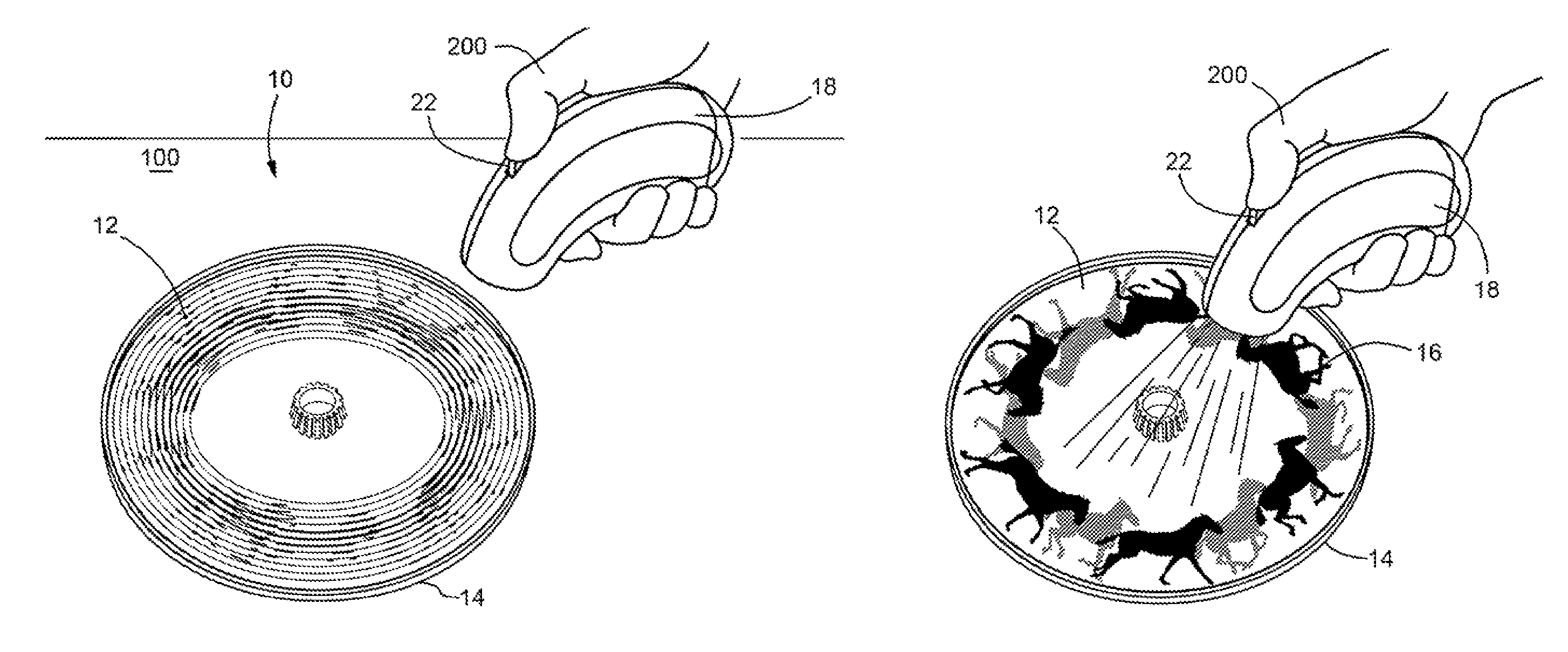
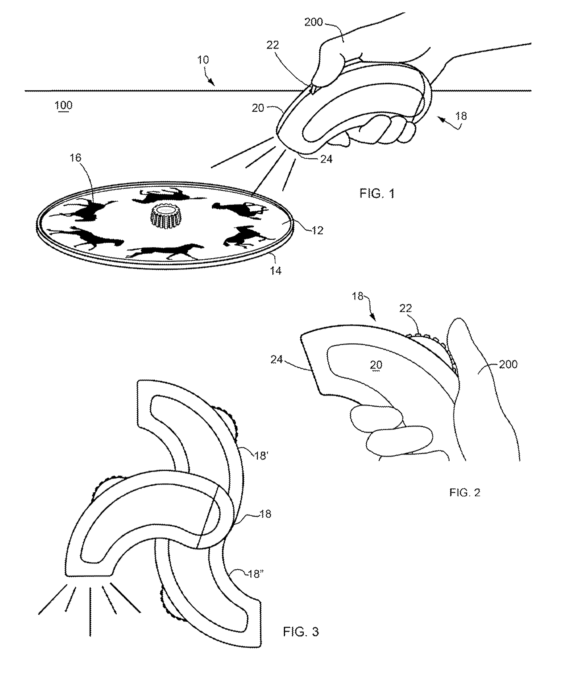
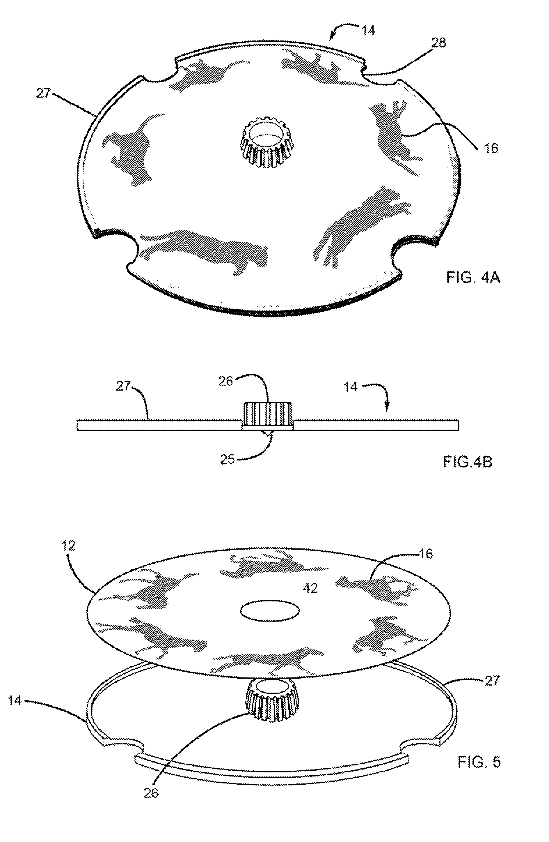
[0031]A stroboscopic animation system pursuant to the present invention is indicated generally at 10 in FIG. 1. The stroboscopic animation system 10 is formed by a handheld stroboscopic light 18 in combination with a manually rotatable top 14 that retains an animation disk 12. The animation disk in FIG. 1 has a cyclic series of images 16 disposed thereon. In this example, the images 16 comprise images of a galloping horse and are disposed with an orientation generally perpendicular to the respective radii of the animation disk 12. As described further hereinbelow, the stroboscopic light 18 has a pistol-han...


PUM


Abstract

A stroboscopic animation system with a handheld stroboscopic light with a light source that emits stroboscopic flashes, a manually rotatable top, and images to be animated retained on the upper surface of the top, such as on an animation disk. The frequency of the stroboscopic flashes can be varied, such as by a rotatable dial, with the “on” portions remaining constant and the “off” portions being adjusted. The flashes can have a lower limit of 10 to 20 flashes per second and an upper limit of 100 to 110 flashes per second, the “on” portions of the flashing sequence can be between one-900th and one-1100th of a second, and the luminous intensity of the light source can be between 65 and 130 foot candles. An orientation switch can automatically induce an “off” condition when the light is disposed outside a predetermined angular range of orientation.

Description

FIELD OF THE INVENTION[0001]The present invention relates generally to animation devices. More particularly, disclosed herein is a stroboscopic animation system wherein images applied to a manually rotatable top can be selectively animated by use of a handheld stroboscopic light source.BACKGROUND OF THE INVENTION[0002]A zoetrope produces the illusion of motion from a rapid succession of static pictures. A typical zoetrope employs a rotatable cylinder with vertical slits cut into its sides. A band including a series of images, which can be drawings or photographs, is placed within the cylinder to be viewed through the slits. The cylinder can then be rotated while the viewer looks through the slits at the images on the opposite side of the cylinder's interior.[0003]As the viewer sees the images pass by an individual slit, the illusion of motion is perceived. This illusion of motion depends on two things: persistence of vision and the phi phenomenon. Persistence of vision derives from ...

Claims


Application Information

Patent Timeline
IPC IPC(8): G03B25/00
CPCG09F19/12G03B25/00G09F2013/1886
Inventor SEDER, RUFUS BUTLER
Owner SEDER RUFUS BUTLER
Why Eureka
Try Eureka