
Laser obstacle monitoring control system between shield door and train door on subway station platform

A subway platform, monitoring and control technology, used in railway car body parts, stations, door/window accessories, etc., can solve the problems of inaccuracy, poor reliability, and insensitive infrared detection instruments, and achieve high power, good directionality, Avoid overlapping effects

Active Publication Date: 2009-06-24
沈阳睿能科技有限公司
View PDF0 Cites 20 Cited by
  • Summary
  • Abstract
  • Description
  • Claims
  • Application Information

AI Technical Summary

Problems solved by technology

[0006] The purpose of the present invention is to provide an accurate, sensitive, easy-to-operate, and safety-performing system for the problems of insensitivity, inaccuracy, and poor reliability of infrared detection instruments that exist between the current subway platform screen door and the train door. , High reliability laser obstacle monitoring and control system between the subway platform screen door and the train door

Method used


Image

  • Laser obstacle monitoring control system between shield door and train door on subway station platform
  • Laser obstacle monitoring control system between shield door and train door on subway station platform
  • Laser obstacle monitoring control system between shield door and train door on subway station platform

Examples


Embodiment 1

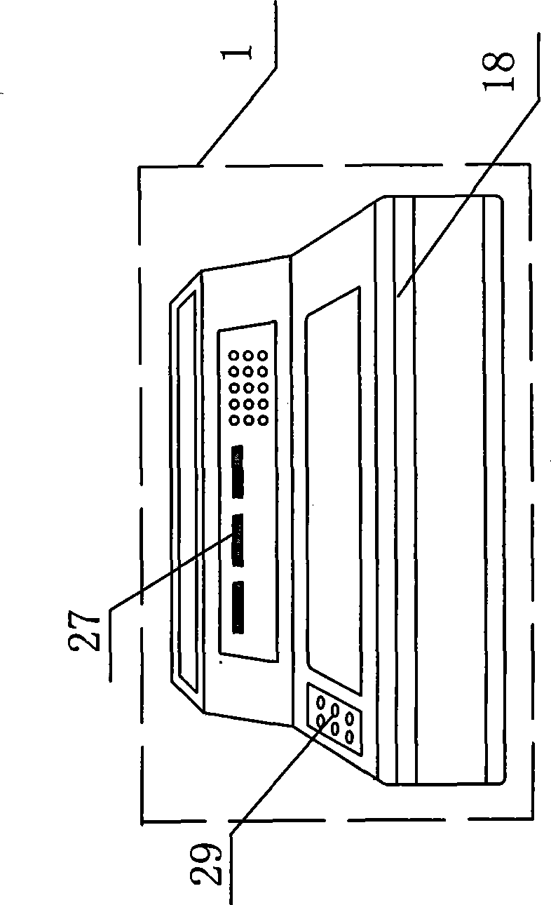
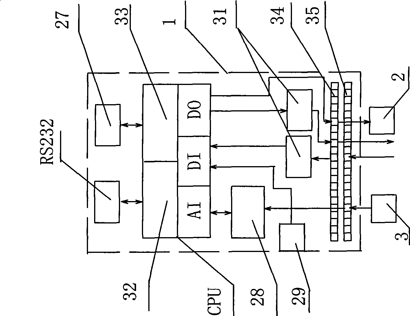
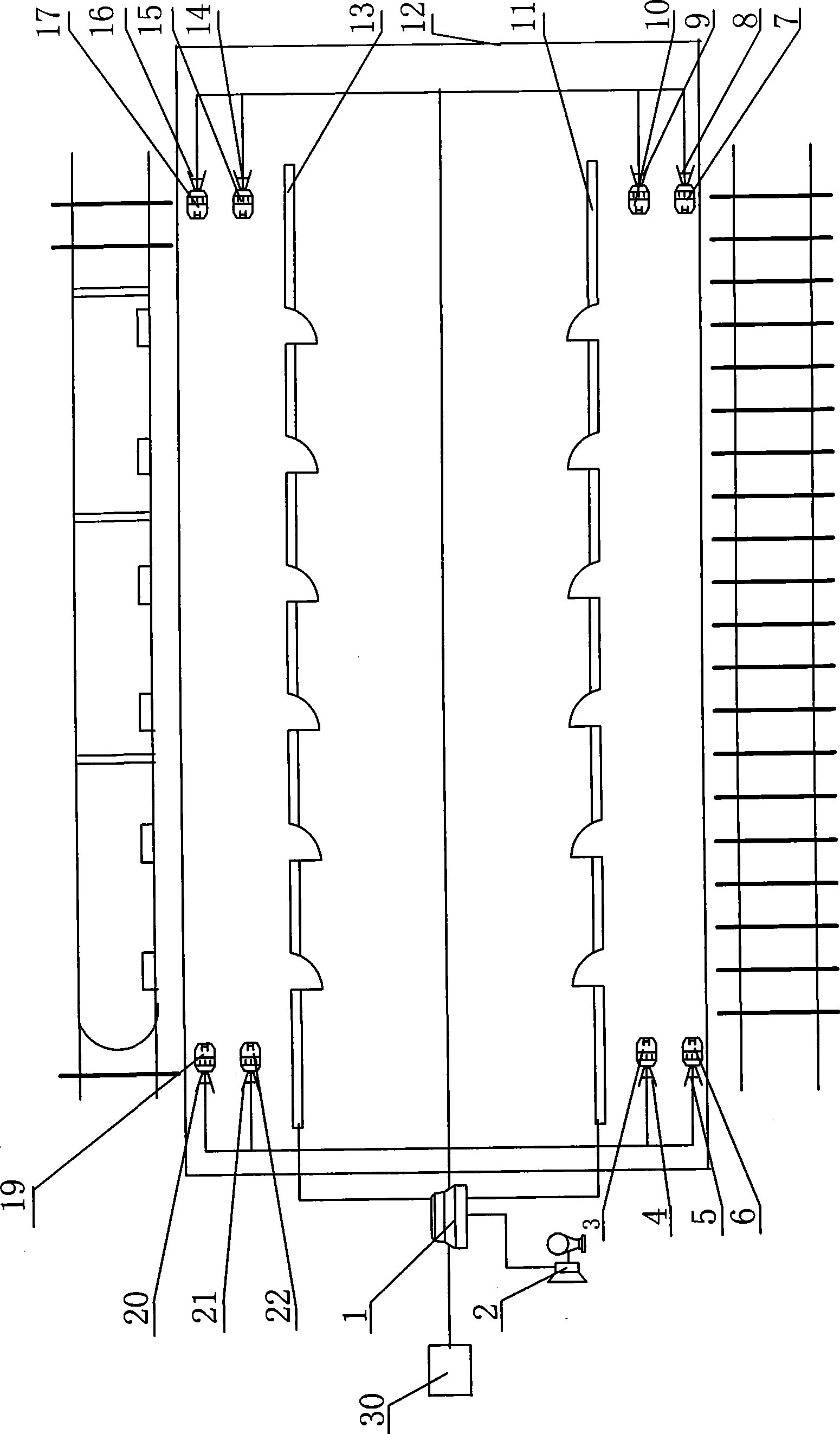
[0038] The laser obstacle monitoring and control system between the screen door of the subway platform and the train door includes hardware and software. The hardware part includes a monitoring unit, a control unit, and an alarm unit; the control unit includes a controller 1; the controller 1 is the The key equipment of the invention, the controller includes a box body 18 and a CPU module installed in the box body 18, a liquid crystal terminal 27, a signal isolator 28, a button 29 and a safety relay 31; the CPU module is composed of an AI unit, a DI unit and a DO unit. Composition: No. 1 communication interface 32 of the CPU module is connected with the RS232 communication interface, No. 2 communication interface 33 of the CPU module is connected with the LCD terminal 27, and the LCD terminal 27 is set and displays multiple pictures; the relevant terminal of the AI ​​unit of the CPU module The pin is connected to the corresponding terminal of the signal isolator 28, the relevan...

Embodiment 2

[0045] Embodiment 2 is basically the same as Embodiment 1, except that No. 1, No. 2, No. 3 and No. 4 laser emitters 3, 6, 19 and 22 adopt the model SXD-JG-B, which has the ability to emit laser Can accept the function of the laser reflected back again, so corresponding to it is No. 1, No. 2, No. 3 and No. 4 laser reflectors 23, 24, 25 and 26, No. 1, No. 2, No. 3 and No. 4 laser reflectors 23, 24, 25 and 26 are located on the corresponding rear brackets.


PUM


Abstract

The invention relates to a laser detection and control system for barriers between a shield door of a metro platform and a train door, comprising a monitoring unit, a control unit and an alarm unit, wherein, the controller comprises a CPU module, a liquid crystal terminal, a signal isolator, buttons and a safety relay; generating lasers are respectively installed on a front bracket, and a laser receiver or a laser reflection plate is installed on a rear bracket corresponding to the front bracket; the control ends of the generating lasers are connected with the output end of the controller, and the output end of the laser receiver is connected with the input end of the controller; the corresponding output end of the controller is correspondingly connected with the control input end of the shield door; and the corresponding output end of the controller is connected with a buzzer and a caution light of the platform. The laser detection and control system realizes the intelligent operation of judging the existence of barriers between the shield door of the metro platform and the train door, has the advantages of compact integral structure, reasonable cost, easy and convenient installation, simple and intelligent operation, stable and reliable performance, higher practicability and favorable development prospect, and is applicable to metro platform.

Description

technical field [0001] The invention relates to a monitoring and control system, in particular to a laser obstacle monitoring and control system for detecting whether there is an obstacle between a screen door of a subway platform and a train door, and providing an accurate signal for safe departure of a train. Background technique [0002] As an important transportation facility in modern cities, subway has become the main development direction of public transportation in big cities due to its advantages of fast, punctual, convenient and comfortable. For safety, most of present subway platforms are provided with a screen door, that is, a barrier with a door that is convenient for passengers to ride. [0003] Installing the screen door on the subway platform is a necessary facility in the development of subway construction. The screen door isolates the platform from the train operation area, and automatically controls the opening and closing of the door. It can not only prov...

Claims


Application Information

Patent Timeline
Patent Type & Authority Applications(China)
IPC IPC(8): E05F15/20E06B5/10B61B1/02E05F15/73
Inventor 张毓海刘红兵张小明李永明刘叶冰
Owner 沈阳睿能科技有限公司
Learn More