Front-loading display system

a display system and front-loading technology, applied in the field of picture frames, can solve the problems of frame safety issues, children's use, and the use of glass lenses in known picture frames, and achieve the effect of quick and frequent change of displayed objects and improved safety features

Active Publication Date: 2013-07-16
SPLITTGERBER UTE
View PDF6 Cites 18 Cited by
  • Summary
  • Abstract
  • Description
  • Claims
  • Application Information

AI Technical Summary

Benefits of technology

[0009]In a preferred embodiment, the current display system allows the user to quickly and frequently change displayed objects. In another preferred embodiment, the present display system offers improved safety features over existing devices. Together these characteristics make it possible for the present invention to be used by children and may also offer advantages for people with certain disabilities.

Problems solved by technology

Such picture frames often bear safety issues and are not designed for straight-forward assembly and disassembly, which prevents them from being used by children.
The glass lens frequently used in known picture frames presents an additional hazard during assembly and use.
These tabs frequently break off or come loose, rendering the assembly less useful.
In addition, such tabs often contain sharp edges, which may cause injury to the user.
Each time artwork is inserted into the picture frame the clasps have to be removed, which typically requires significant pressure to be applied.
As a result, such fastening mechanism is not suitable for use by children.
In this respect, the known devices offer little advantage over traditional picture frames.
However, even when using the described aids, it is cumbersome to position a non-rigid picture onto a vertical surface, especially if the picture frame is mounted at a difficult to reach location.
In addition, the required procedure may damage the artwork.

Method used


Image

  • Front-loading display system
  • Front-loading display system
  • Front-loading display system

Examples


Embodiment Construction

I. Introduction

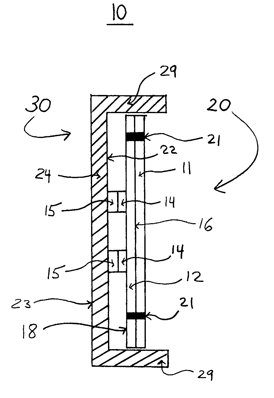
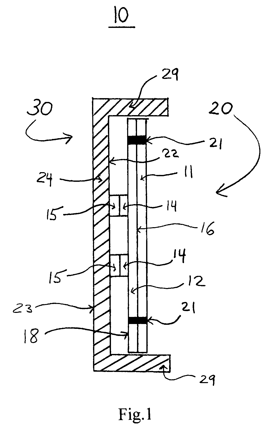
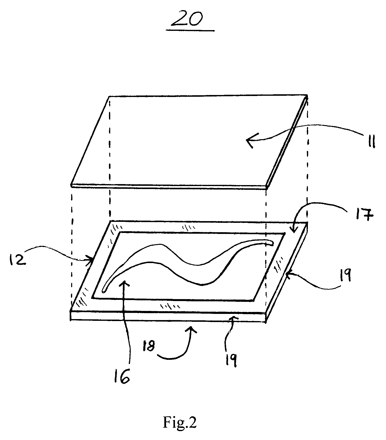
[0022]The present invention provides a front-loading display system including a base and an object-holding assembly. In a preferred embodiment, the object-holding assembly can be releasably attached to the base using a fastener described herein. A preferred fastener employs magnetic force. An exemplary object-holding assembly includes a resting plate and a cover plate and optionally a display object, which is placed between the resting plate and the cover plate. The resting plate and the cover plate are releasably attached to each other using one or more holding device. An exemplary holding device is selected from clips, clasps, clamps, braces, hinges, elastic bands, corner casts and the like.

[0023]The display system of the invention offers a variety of advantages over traditional picture frames as well as known, front-loading devices. One advantage is that the base does not need to be removed from the mounting surface (e.g., a wall) in order to add, change or remove ...


PUM


Abstract

The subject matter of the current invention is directed to a front-loading display system adapted for safe, frequent, and rapid change of displayed objects. The display system includes a base and an object-holding assembly. The object-holding assembly can be releasably attached to the base through the use of a fastener, which allows the base to remain mounted to a mounting surface when changing display objects. In a preferred embodiment, the fastener employs magnetic force to connect the base and the object-holding assembly. The display object is retained between a resting plate and a cover plate, the two plates being releasably attached to each other by the use of at least one holding device, which may be selected from clips, clasps, hinges and elastic bands.

Description

CROSS REFERENCE TO RELATED APPLICATIONS[0001]This application claims priority under 35 U.S.C. §119(e) to U.S. Provisional Patent Application No. 60 / 778,826 filed Mar. 3, 2006, which is incorporated herein by reference in its entirety for all purposes.BACKGROUND OF THE INVENTION[0002]A wide variety of picture frames exist. Known picture frames typically include a frame, a transparent lens and a backing, which is mounted to the frame in order to retain the artwork between the backing and the lens. The backing is typically a heavy cardboard, and optionally includes a hinged leg for upright display on a horizontal support, such as a tabletop. The backing or frame commonly includes wall-mounting means such as metal loops or wire for mounting over a picture hanger (e.g., a hook), a nail or a screw driven into the wall.[0003]Conventional picture frames are loaded from the backside by removing the backing, placing the artwork on the clear lens and re-attaching the backing. Such picture fram...

Claims


Application Information

Patent Timeline
Patent Type & Authority Patents(United States)
IPC IPC(8): A47G1/06
CPCA47G1/06A47G2001/0666A47G2001/0672
Inventor SPLITTGERBER, UTE
Owner SPLITTGERBER UTE
Why Eureka
Try Eureka