Universal bore sight

a universal bore and sight technology, applied in the field of optical sighting devices, can solve problems such as inapplicability of bore sights

Active Publication Date: 2013-07-16
SELLMARK CORP
View PDF34 Cites 19 Cited by
  • Summary
  • Abstract
  • Description
  • Claims
  • Application Information

AI Technical Summary

Benefits of technology

[0009]In accordance with yet another aspect of the present invention, the bore sight has a spring to urge the arbor in the first direction and into the bore of the member. The housing can have a magnet at the planar surface to secure the bore sight in engagement with the member. A laser can be mounted in the housing that projects a beam aligned with the centerline of the bore when the bore sight is aligned with the member. Circuitry, a battery and a switch to operate the laser can be mounted in the housing. The arbor can be made of material that will not damage the member, such as brass or plastic.

Problems solved by technology

Even so called universal bore sights are not useable on all calibers without multiple attachments.

Method used


Image

  • Universal bore sight
  • Universal bore sight
  • Universal bore sight

Examples


first embodiment

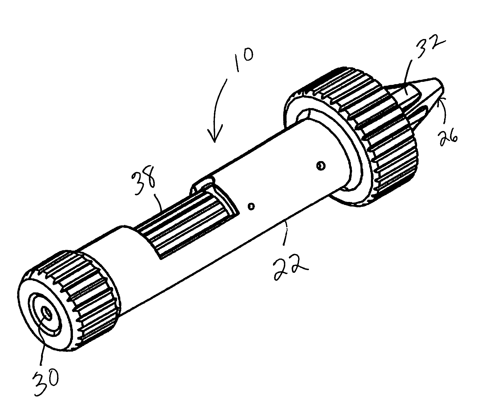
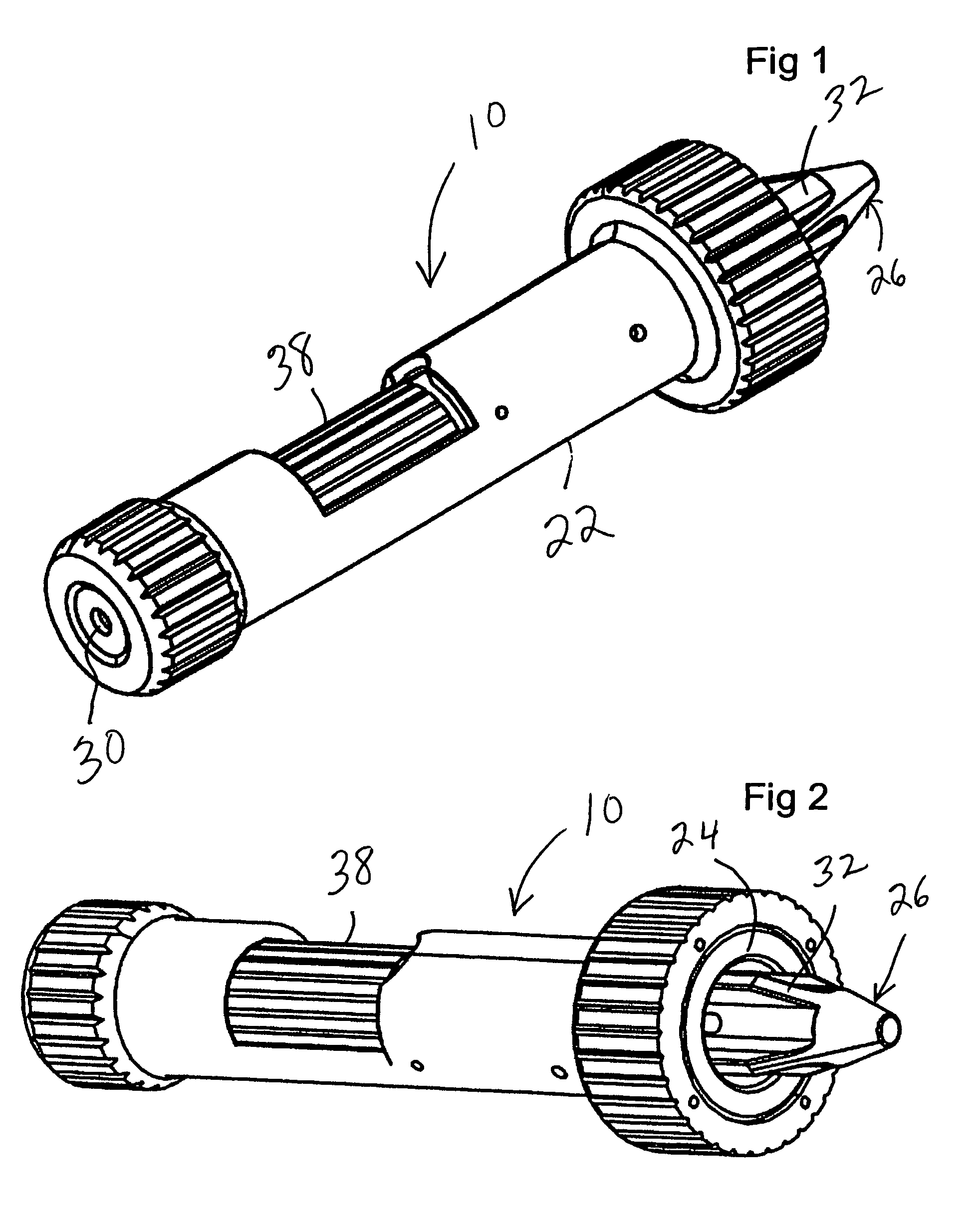
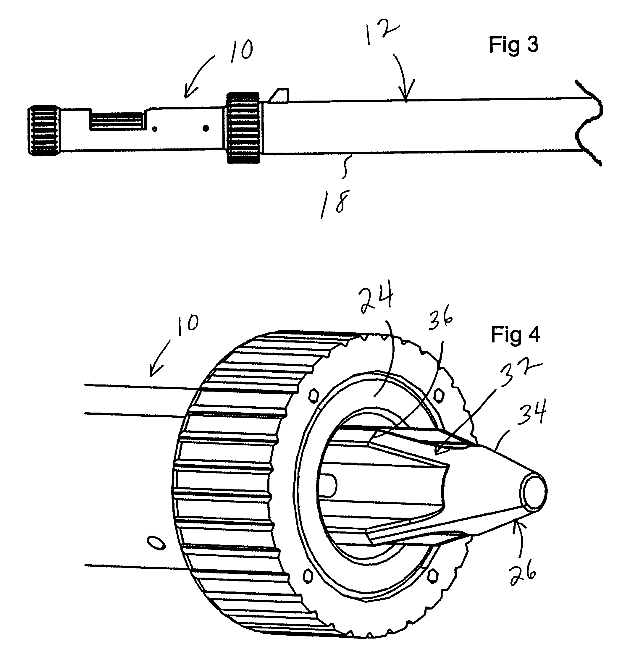
[0018]With reference now to the figures, FIGS. 1-6 illustrate a bore sight 10 forming the present invention. The bore sight 10 is used to align optical sighting devices, such as telescopic sights mounted on a firearm 12, by projecting a laser beam aligned with the centerline 14 of the bore 16 of the barrel 18 of the firearm 12. As will be described hereinafter, the bore sight 10 is secured on the end 20 of the barrel 18 during use, preferably by magnetic force. A significant advantage of the bore sight 10 is that it can be used without modification on a range of bore diameters, or calibers. Preferably, the bore sight 10 can be used with calibers in a range of .17 caliber to .50 caliber, corresponding to a diameter from 0.17 inches to 0.50 inches, with either rifles or handguns.

[0019]The bore sight 10 includes a housing 22, which includes a magnetic alignment face 24 for attachment to the end 20 of the barrel 18, and an arbor 26 which is urged into the bore 16 by a spring 28 within t...

second embodiment

[0025]With reference to FIGS. 7 and 8, a bore sight 100 forming the present invention will be described. The bore sight 100 does not include an arbor 26, but in all other aspects is identical to bore sight 10. In use, the magnetic alignment face 24 of the bore sight 100 is positioned on the end 20 of the barrel 18 and the bore sight 100 is hand centered to align with the centerline 14 of the bore 16. The laser dot generated by the laser 30 inside bore sight 100 is large enough at 100 yards to cover any discrepancies + or −5 mm from the centerline 14 and the bore sight 100.


PUM


Abstract

A bore sight (10) is provided that can be used with many calibers of firearms (12) to align optical devices such as rifle scopes. The bore sight (10) has a housing (22) with a spring loaded arbor (26) extending from one end thereof. The arbor (26) has a tapered face (32) varying in diameter in a range including popular calibers, such as .17 to .50 caliber. The arbor (26) is inserted in the end (20) of the barrel (18) as far as the caliber of the barrel (18) permits. The arbor (26) then starts retracting into the housing (22) against the spring force to allow the magnetic alignment face (24) of the housing to move into contact with the end (20) of the barrel to align the bore sight (10) and laser (30) with the bore (16).

Description

CROSS REFERENCE TO RELATED APPLICATIONS[0001]This application is a continuation of U.S. patent application Ser. No. 12 / 221,795 filed Aug. 6, 2008, which claims priority from Provisional Patent Application Ser. No. 61 / 025,784 filed Feb. 3, 2008.TECHNICAL FIELD[0002]This invention relates to an optical sighting device, particularly for a firearmBACKGROUND OF THE INVENTION[0003]Quite often, firearms use optical sighting devices, such as telescopic rifle scopes, for more accurate targeting. In order to align these sighting devices with the physical point of impact of the bullet at a given range, laser bore sighting devices are often used, such as disclosed in U.S. Pat. No. 5,432,598.[0004]Laser bore sights currently use two methods of attachment to the firearm. The first method has a tapered arbor that centers the laser to the firearm bore via the muzzle bore, as in U.S. Pat. No. 5,432,598. A second method allows the laser bore sighter to take the shape of a bullet casing and to be inse...

Claims


Application Information

Patent Timeline
Patent Type & Authority Patents(United States)
IPC IPC(8): F41G1/54
CPCF41G1/54
Inventor SELLERS, JAMES J.MELLON, WILLIAM K.DAOHAI, LI
Owner SELLMARK CORP
Why Eureka
Try Eureka