Ventilator to tracheotomy tube coupling

a technology of tracheotomy tube and ventilator, which is applied in the field of medical equipment, can solve the problems of increasing the likelihood of infection-causing secretions, increasing the likelihood of infection, and less secure, so as to and reduce the likelihood of exertion of excessive axial for

Inactive Publication Date: 2013-07-16
LAZARUS MEDICAL
View PDF60 Cites 30 Cited by
  • Summary
  • Abstract
  • Description
  • Claims
  • Application Information

AI Technical Summary

Benefits of technology

[0011]In accordance with the invention, a coupling is provided for connecting a ventilator tube to a tracheotomy tube. The ventilator tube has a connector at its leading end and the tracheotomy tube has a tapered tubular extension on its trailing end. The coupling is a preferably expandable, flexible tubular member with a first adapter on its trailing end for connecting its trailing end in a pneumatic flow path to the ventilator tube leading end connector and a second adapter on its leading end for mating its leading end in a pneumatic flow path with the trailing end of the tracheotomy tube. The second adapter has a latching mechanism for engaging the leading end of the coupling to the tracheotomy tube to prevent the leading end of the tubular member from axially displacing from the trailing end of the tracheotomy tube after they have been mated in the pneumatic flow path. An unlatching mechanism is provided for disengaging the latching mechanism from the tracheotomy tube so as to permit the leading end of the tubular member to axially displace from the trailing end of the tracheotomy tube. The unlatching mechanism is operated by non-axial forces so that the coupling can be disengaged from the tracheotomy tube without exertion of excessive axial force on the patient's neck.
[0014]Known child tracheotomy tubes have a tubular extension on their trailing end. For such tracheotomy tubes, the coupling tubular member has a first means for mating the leading end of the tubular member in the pneumatic flow path with the tubular extension of the tracheotomy tube by motion of the mating means in a generally axial direction relative to the tubular extension. A second means is provided on the mating means for engaging with the tracheotomy tube to prevent the leading end of the tubular member from axially displacing from the tubular extension after mating. A third means is provided on the mating means which is operable by application of force on the mating means in other than the generally axial direction for disengaging the engaging means from the tracheotomy tube to permit the tubular member to axially displace from the tubular extension of the tracheotomy tube. The mating means consists of a nozzle insertable into the tubular extension. The engaging means consists of a clamshell, the clamshell and the tubular extension having complementary three-dimensional surfaces which prevent axial displacement of the clamshell from the tubular extension gripped therein. Half of the clamshell has diametrically opposite lugs and another half of the clamshell has diametrically opposite fingers which resiliently snap over the lugs when the clamshell is closed. The disengaging means consists of means on the fingers for spreading the fingers in response to inward radial pressure on the spreading means to release the lugs.
[0016]To connect the improved child's tracheotomy tube to a ventilator tube, the coupling provided has a tubular member adapted at its trailing end for connection in a pneumatic flow path to the ventilator tube leading end connector. The leading end of tubular member is adapted for mating the tubular member in the pneumatic flow path with the tubular extension of the tracheotomy tube by motion of the mating means in a generally axial direction relative to the tubular extension. The leading end of the tubular member is further adapted for engaging with one of the circumferential sets of serrations to prevent the leading end of the tubular member from axially displacing from the tubular extension after mating. The leading end of the tubular member is further adapted to be operable by application of force in other than the generally axial direction for disengaging the leading end of the tubular member from the engaged circumferential set of serrations to permit the leading end of the tubular member to be axially displaced from the tubular extension of the tracheotomy tube. Preferably, the trailing end adaptation of the tubular member is a hard annular ring on its trailing end, the ring having a tubular concentric rearward extension, a sleeve mounted for rotation on the extension and a stop mechanism on the extension for preventing the sleeve from axially displacing from the extension. This sleeve-on-extension configuration of the of the coupling allows rotational forces exerted on the tracheotomy system to be more likely dissipated at the ventilator end rather than the tracheotomy tube end of the system. Preferably, the leading end mating adaptation is a hard sleeve of inner diameter sized to axially receive the tracheotomy tube tubular extension with the trailing face of the tracheotomy tube extension abutting the trailing interior annular wall of the sleeve. Thus, axial motion is required only for initiation of abutting contact, reducing the likelihood of exertion of such axial force as might be required to create a frictionally tight locking fit. Preferably, the leading end engaging adaptation is a circumferential set of at least two fingers resiliently mounted on and oriented forward of the sleeve for seating in one of the circumferential sets of displaced serrations on the tracheotomy tube annular ring when the trailing face of the tracheotomy tube tubular extension abuts the trailing interior annular wall of the sleeve. Thus, the force exerted to engage the components is primarily radial rather than axial or rotational, reducing the likelihood of exertion of excessive axial force on the system. It is also preferred that disengaging adaptation be squeeze plates on the fingers for radially displacing the fingers to release them from the engaged set of serrations in response to radially inward pressure on the squeeze plates. Thus, the force exerted to disengage the components is also primarily radial rather than axial or rotational, reducing the likelihood of exertion of excessive axial force on the system.

Problems solved by technology

Because of their structural configuration and operational steps, there are some problems inherent in the known one or two piece tracheotomy tubes, in the known flexible connectors and in their combination.
One set of problems is related to the comfort of the patient.
This concern is sometimes addressed by after-market removal of all or a portion of the flange, but this solution generally results in a damaged connector, increasing the likelihood of infection-causing secretions and also becomes less secure due to removal of the firm portion of the connector.
Also, the manipulation of the flange to connect or disconnect the connector to or from the tubular extension can cause considerable discomfort to the patient, since this often requires the application of manual pressure to the patient's neck, chin or chest.
It is common practice to extend rubber bands from one side of a neck plate on the tracheotomy tube collar to the flexible connector and back to the other side of the neck plate in an effort to hold the flexible connector in place, but the rubber bands are likely either too elastic or too inelastic to properly accomplish this purpose.
While a child's tracheotomy tube is smaller than an adult's, the available space between the chin and chest is significantly smaller and the flexible connector flange is the same size as used for adults, so the smaller device affords no relief for the connector flange related comfort problems.
A second set of problems is related directly to the ability, or inability, of the system to accomplish its primary purpose of keeping the patient's trachea connected to the ventilator.
Moreover, the connector and tracheotomy tube parts are always wet and slippery due to the very nature of their application and are not very tightly mated because of the neck pressure problems.
The end result is a connection so tenuous that a mere sneeze, cough or turn or tip of the head can cause the connector and the tapered tubular extension to separate, defeating the operation of the system.
A third set of problems concerns the performance of the medical staff as a result of these other problems.
The inherent comfort issues result in more pains-taking, time-consuming effort by the staff in an effort to reduce the impact of these discomforts on the patient.
And, because of the ease of inadvertent disconnection of the system, the staff unnecessarily spends valuable time monitoring and reconnecting the connectors to the tubular extensions of the tracheotomy tubes.

Method used


Image

  • Ventilator to tracheotomy tube coupling
  • Ventilator to tracheotomy tube coupling
  • Ventilator to tracheotomy tube coupling

Examples


Embodiment Construction

[0055]Tracheal Inserts:

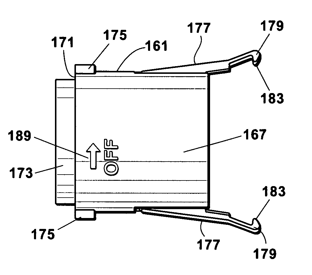
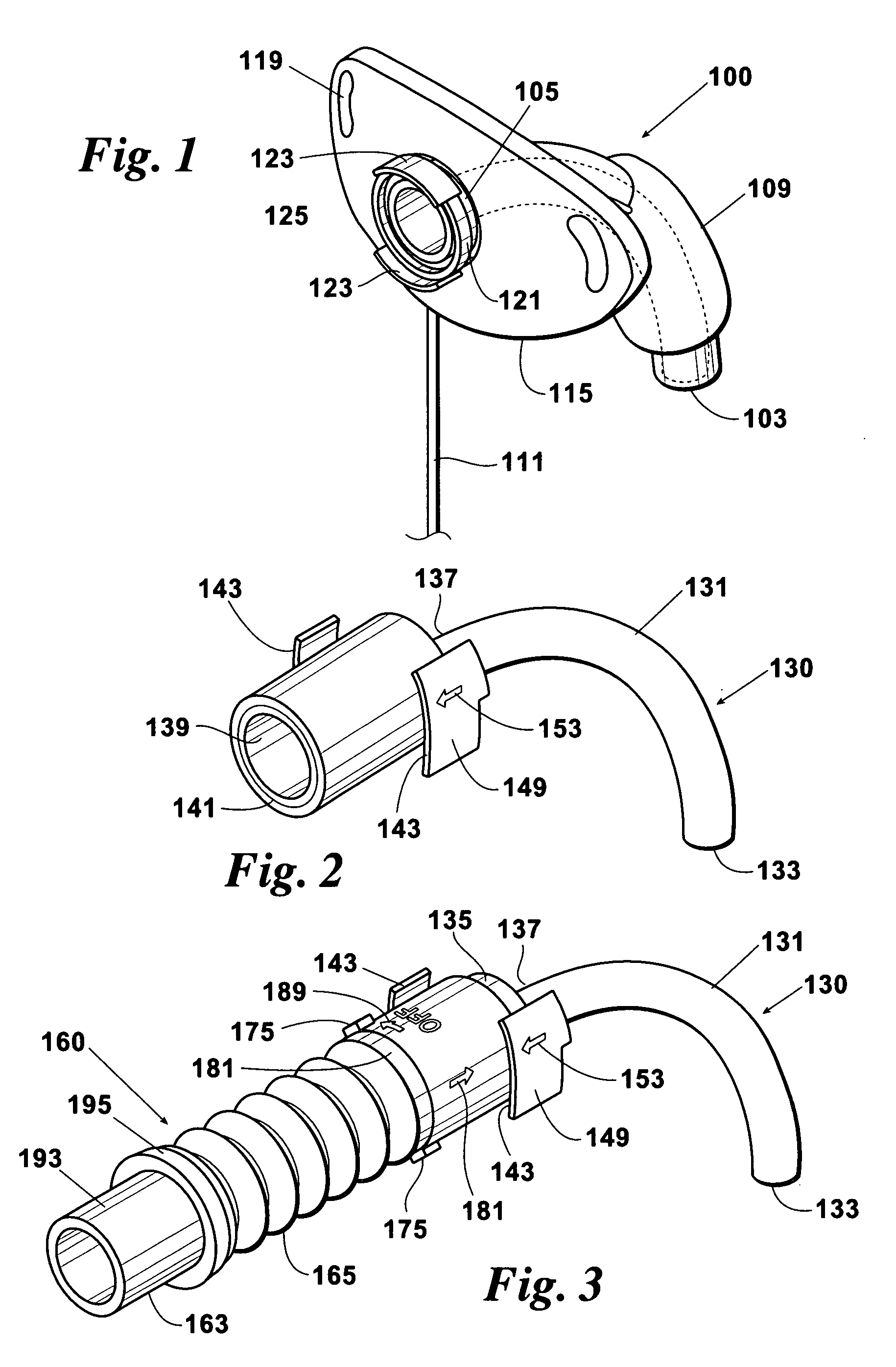
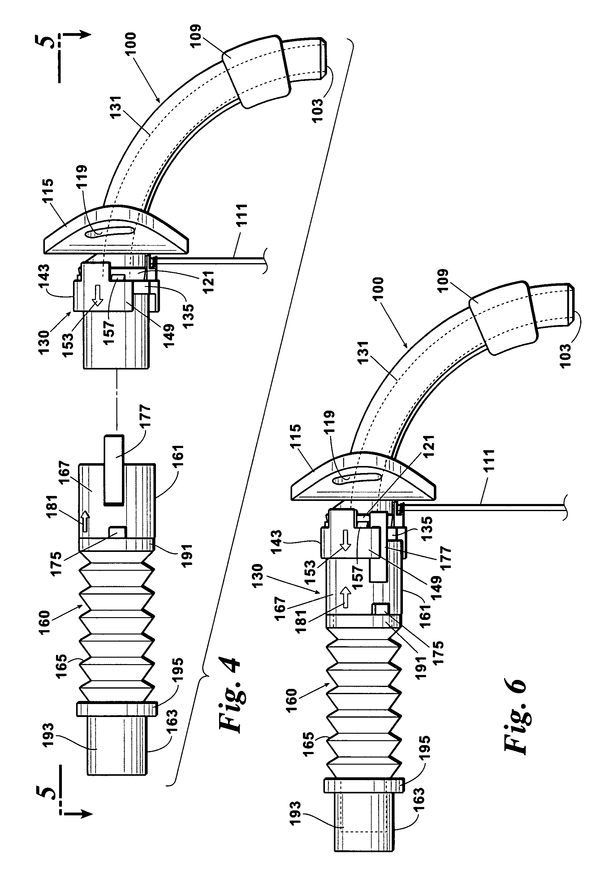
[0056]Adult tracheotomy tubes are illustrated in FIGS. 1-18, showing a tracheotomy tube with outer and inner cannulas 100 and 130 and a tapered tubular extension 139 on the trailing end of the inner cannula 130 and FIGS. 19-26, showing a tracheotomy tube with outer and inner cannulas 200 and 230 and a tapered tubular extension 223 on the trailing end of the outer cannula 200. A child's tracheotomy tube is illustrated in FIGS. 27-35. A child's tracheotomy tube has only one cannula which, for purposes of explanation of the invention is identified as an outer cannula 300.

[0057]All three known outer cannulas 100, 200 and 300 are, in some respects, substantially similar, being arced tubes 101, 201 or 301 of approximately a quarter circle extending from a leading end 103, 203 or 303 to a collar 105, 205 or 305 at the trailing end 107, 207 or 307 of the arced tube 101, 201 or 301. A cuff 109, 209 or 309 on the leading half of the arced tube 101, 201 or 301 is inflata...


PUM


Abstract

A coupling for connecting a ventilator tube to an improved single cannula tracheotomy tube has a latching mechanism which prevents the coupling from inadvertently axially displacing from a tapered tubular extension of the tracheotomy tube after they have been mated in a pneumatically discrete path. Non-axial and non-rotational forces are used to engage and disengage the coupling from the tracheotomy tube. The coupling has a trailing end adapter which permits rotation of the coupling relative to the ventilator tube rather than to the tracheotomy tube.

Description

REFERENCE TO PENDING APPLICATIONS[0001]This application is a continuation-in-part application claiming priority to U.S. patent application Ser. No. 11 / 348,199, filed Feb. 6, 2006, entitled Ventilator to Tracheotomy Tube Coupling.REFERENCE TO MICROFICHE APPENDIX[0002]This application is not referenced in any microfiche appendix.BACKGROUND OF THE INVENTION[0003]This invention relates generally to medical equipment and more particularly concerns devices used to connect ventilators to tracheotomy tubes.[0004]For adult patients, two-piece tracheotomy tubes having inner and outer cannulas are presently in common use. The outer cannula is inserted into the patient's windpipe and the inner cannula is inserted into or removed from the outer cannula for use or for replacement, cleaning or disinfecting, respectively. The outer cannula of these two-piece devices has a collar on its trailing end which is configured to be positively engaged with a collar on the leading end of the inner cannula. T...

Claims


Application Information

Patent Timeline
Patent Type & Authority Patents(United States)
IPC IPC(8): A61M16/00A61M16/08A61M16/04
CPCA61M16/0465A61M16/0488A61M16/0427A61M16/08A61M16/0434Y10T403/59A61M16/0816A61M2205/581A61M16/0875
Inventor WORLEY, BRIAN D.
Owner LAZARUS MEDICAL
Why Eureka
Try Eureka