Stamping-laminating apparatus and method
a technology of stamping and laminating equipment, applied in the direction of mechanical control devices, instruments, process and machine control, etc., can solve the problems of product accuracy deterioration product accuracy deterioration, etc., to improve productivity and reduce product accuracy
- Summary
- Abstract
- Description
- Claims
- Application Information
AI Technical Summary
Benefits of technology
Problems solved by technology
Method used
Image
Examples
first embodiment
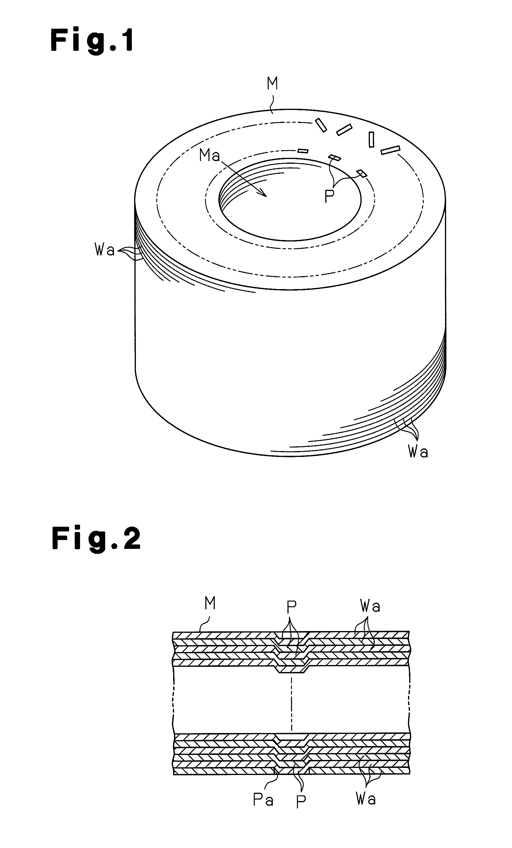
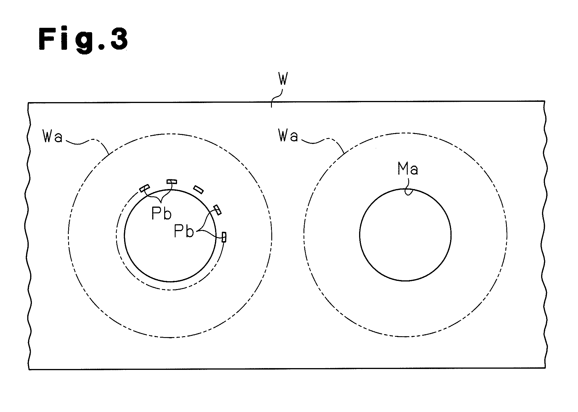
[0027]A first embodiment of the present invention will now be described with reference to FIGS. 4 to 9B.
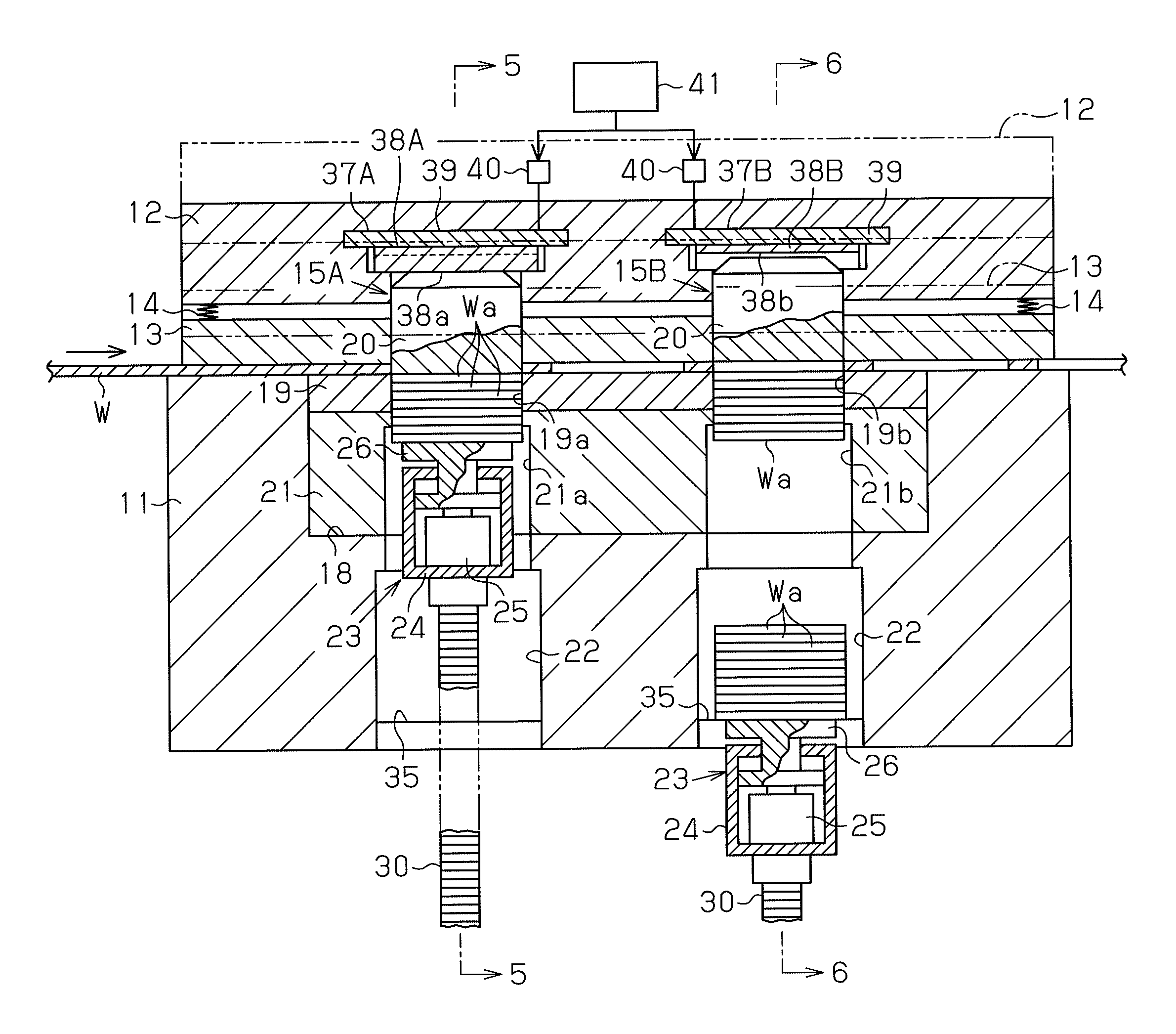
[0028]As shown in FIGS. 4 to 6, a stamping-laminating apparatus includes a workpiece support 11 for supporting a workpiece W. The workpiece W is conveyed along one direction (direction the arrow in FIG. 4) by the workpiece support 11. A lift member 12, which serves as lift means, is provided above the workpiece support 11. A holding member 13 is supported on the lower face of the lift member 12 with springs 14. The holding member 13 is movable relative to the lift member 12 along the direction in which the lift member 12 is lifted and lowered. The springs 14 urge the holding member 13 downward. With the workpiece W placed thereon, the workpiece support 11 is tightly held between the holding member 13 and the workpiece support 11 when the lift member 12 is lowered.
[0029]Two punching structures 15A, 15B, which serve as punching means, are located between the workpiece support 11 and...
second embodiment
[0050]A stamping-laminating apparatus according to a second embodiment of the present invention will now be described with reference to FIGS. 10A and 12D. In the description of the second and subsequent embodiments, the differences from the first embodiment will mainly be discussed.
[0051]The second embodiment is intended to prevent loss of material and loss of time that occur when the punches 20 are switched after stamping of a predetermined number (100 pieces) has been completed. In the first embodiment, as shown in FIG. 9A, after stamping a predetermined number of pieces is completed in the upstream punching structure 15A, the workpiece W has to be moved without being stamped by three pitches before stamping is started again in the downstream punching structure 15B. As shown in FIG. 9B, even if stamping at the punching structure 15A is started immediately after punching a predetermined number of pieces has been completed by the punching structure 15B, there is an unprocessed porti...
third embodiment
[0057]A third embodiment of the present invention will now be described with reference to FIGS. 13A to 13D.
[0058]In the third embodiment, selection switching cams 38A, 38B of selecting mechanisms 37A, 37B are arranged along a direction perpendicular to the direction in which a workpiece W is conveyed, and connected to each other with a coupling portion 45. On the lower face of the selection switching cam 38A that corresponds to the upstream punching structure 15A, a protruding cam surface 38a, a recessed cam surface 38b, a protruding cam surface 38a, and a recessed cam surfaces 38b are formed in the order from the lower side as viewed in FIG. 13. On the lower face of the selection switching cam 38B that corresponds to the downstream punching structure 15B, a protruding cam surface 38a, a protruding cam surface 38a, and a recessed cam surface 38b are formed in this order from the lower side as viewed in FIG. 13.
[0059]Actuators 40 such as motors switch the selection switching cams 38A...
PUM
| Property | Measurement | Unit |
|---|---|---|
| distance | aaaaa | aaaaa |
| pressure | aaaaa | aaaaa |
| lateral pressure | aaaaa | aaaaa |
Abstract
Description
Claims
Application Information
 - R&D
- Intellectual Property
- Life Sciences
- Materials
- Tech Scout
- Unparalleled Data Quality
- Higher Quality Content
- 60% Fewer Hallucinations
Browse by: Latest US Patents, China's latest patents, Technical Efficacy Thesaurus, Application Domain, Technology Topic, Popular Technical Reports.
© 2025 PatSnap. All rights reserved.Legal|Privacy policy|Modern Slavery Act Transparency Statement|Sitemap|About US| Contact US: help@patsnap.com


