Structural joint for a commercial vehicle frame and a frame made with a structural joint

a technology for structural joints and commercial vehicles, applied in the field of structural joints for commercial vehicles and frame components, can solve the problems of destroying the joint and/or the fastener system, bolts and nuts are not usually considered to be as secure, and the disassembly of such joints involves significant effort, so as to achieve the effect of easy assembly and disassembly and easy disassembly of joints

Inactive Publication Date: 2013-07-16
VOLVO GROUP NORTH AMERICA
View PDF22 Cites 7 Cited by
  • Summary
  • Abstract
  • Description
  • Claims
  • Application Information

AI Technical Summary

Benefits of technology

[0003]It would be advantageous to design and make a commercial vehicle frame comprising various structural segments or units, each designed for the load or service demands placed on the commercial vehicle frame. Such an approach allows for improvements in assembly and service, including the use of modular frame units, which can be assembled elsewhere and brought as a unit to the assembly line. In addition, a segment approach allows for the redesign of the frame to decrease weight, which can improve fuel mileage of the vehicle. Moreover, frame segments of various materials and material properties (e.g., stiffness, weight) may be selected, with segments located along the frame's length to achieve an appropriate combination of mass, strength and durability.
[0005]For the purposes of manufacturing efficiency and aftermarket serviceability, it is advantageous if the interface joint is easily assembled and disassembled.

Problems solved by technology

Rivets and welding are generally considered “permanent” structural joints, as disassembly of such joints involves significant effort and usually to some degree destruction of the joint and / or the fastener system.
However, bolts and nuts are not usually considered to be as secure as rivets.

Method used


Image

  • Structural joint for a commercial vehicle frame and a frame made with a structural joint
  • Structural joint for a commercial vehicle frame and a frame made with a structural joint
  • Structural joint for a commercial vehicle frame and a frame made with a structural joint

Examples


Embodiment Construction

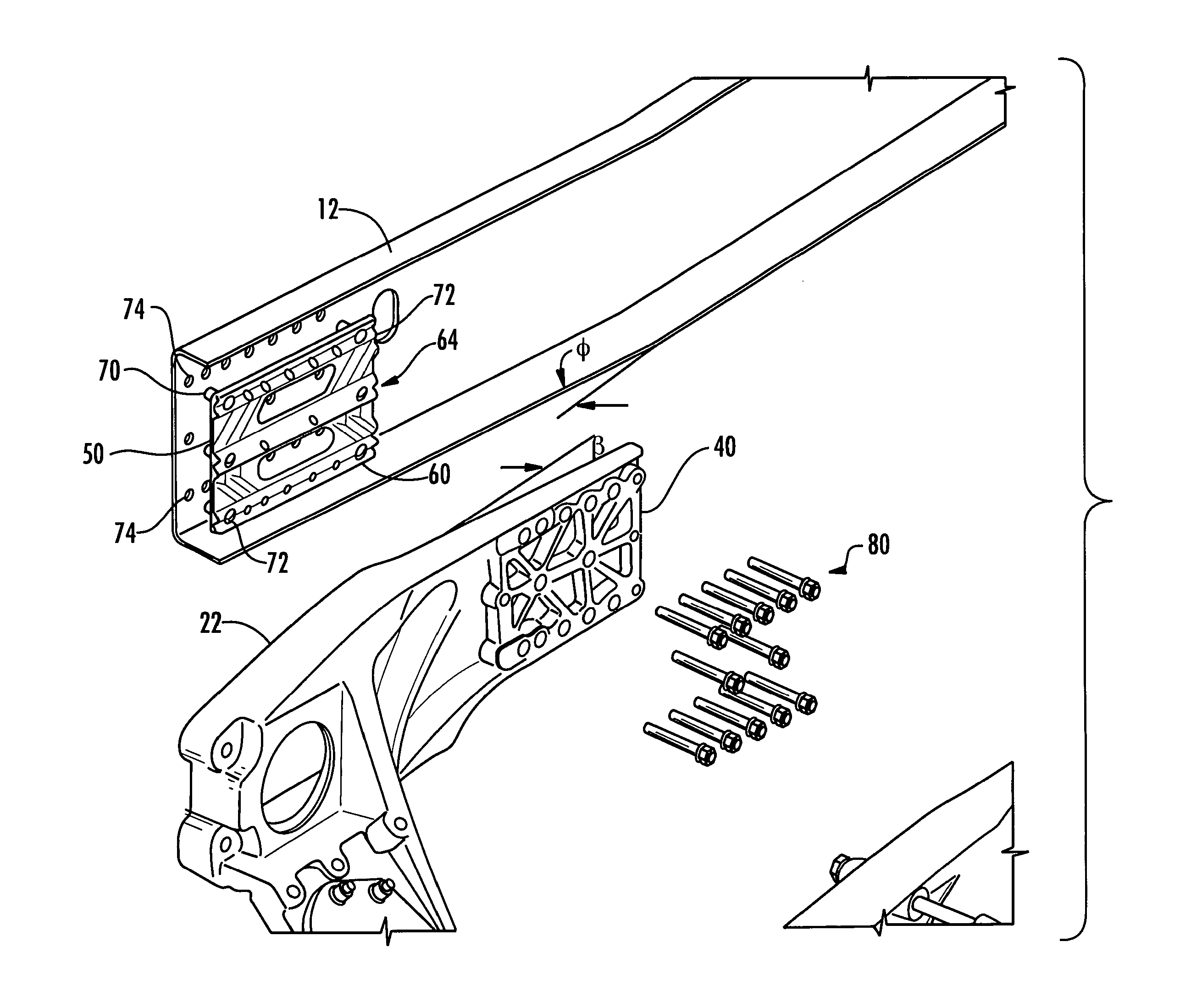
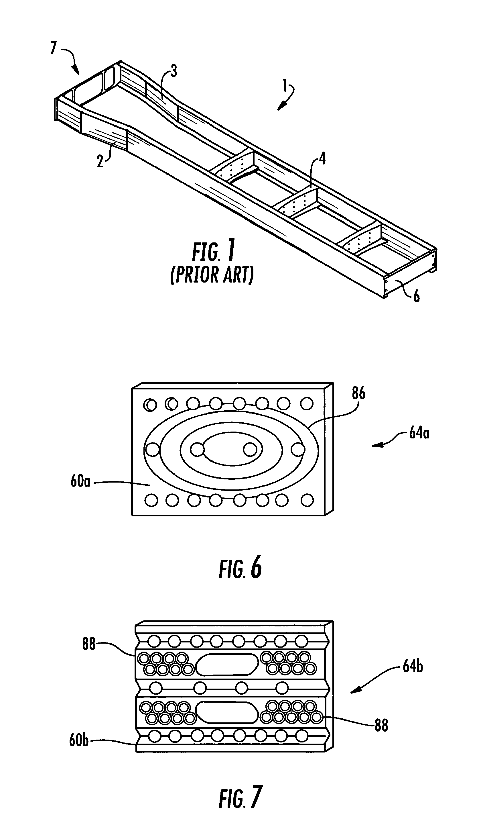
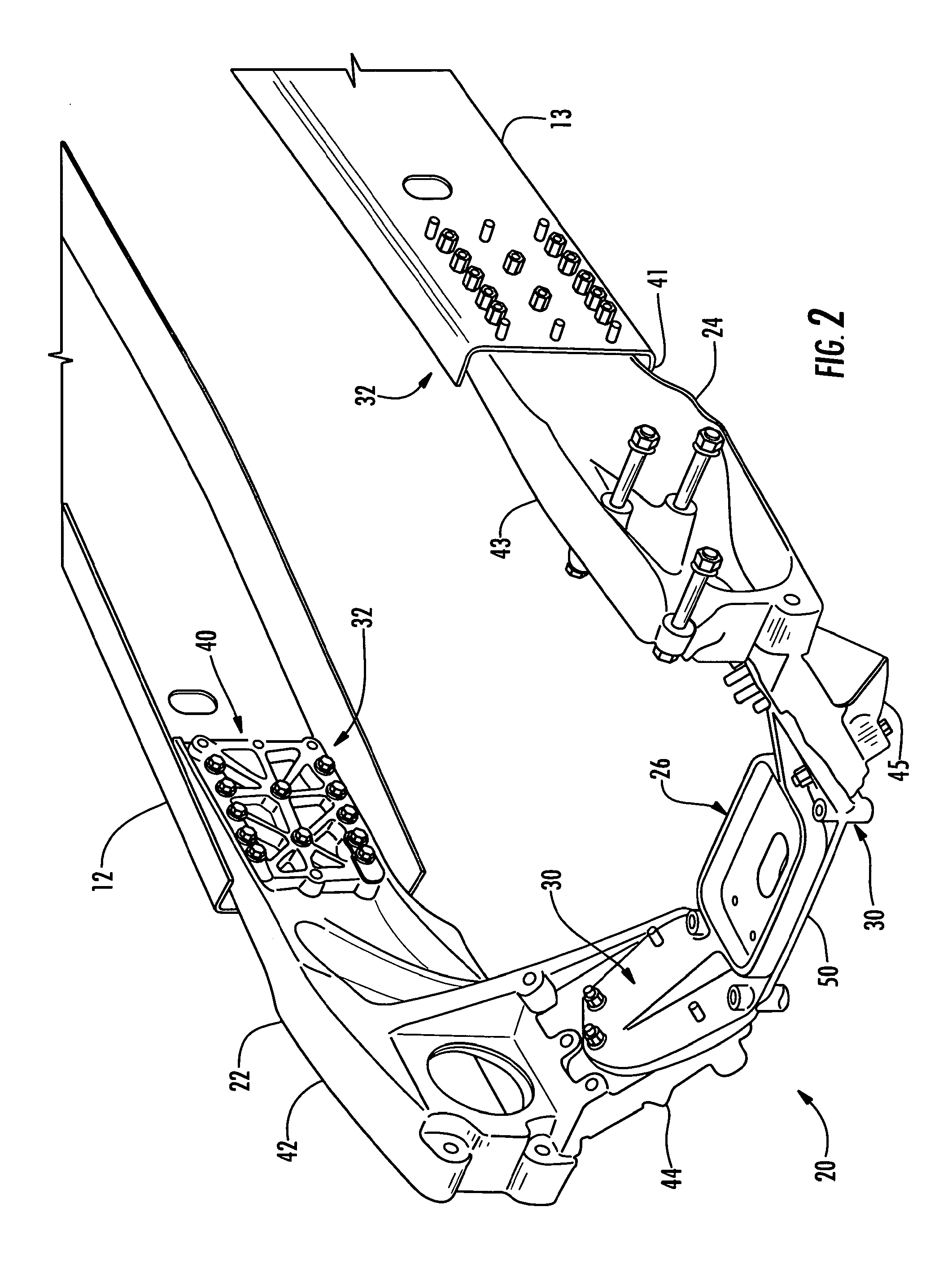
[0025]A conventional frame 1 for a heavy truck is shown in perspective view in FIG. 1. The frame 1 is formed of two frame rails 2, 3 joined by cross members 4 (three cross members are shown) and end cross member 6 to form a rigid, weight bearing structure. The frame rails 2, 3 are elongated U-shaped members, typically formed from steel sheet. The frame 1 shown in FIG. 1 has a front end portion 7 where the frame rails are bent to diverge to'enlarge the space therebetween to accommodate a vehicle engine.

[0026]The frame 1 is intended to support a number of components which are mounted directly or indirectly to the frame. An engine cradle assembly (not shown in FIG. 1) is mounted at the front end 7 and spans between the frame rails 2, 3. A front bumper assembly may also be mounted to the front ends of the frame rails. In addition, the front ends of the frame rails may also support a radiator mounting assembly. The frame also supports the vehicle axles and suspension, the cab, and the fi...


PUM


Abstract

A structural joint in a truck tractor frame includes a first frame member having an interface plate permanently mounted thereon, the interface plate having an interface surface contoured with a plurality of protrusions and depressions, which may be grooves and ridges. A second frame member has an interface surface contoured with a plurality of protrusions and depressions complementary to the plurality of protrusions and depressions of the interface surface of the interface plate. The second frame member is mounted to the first frame member with the interface surfaces in contact, with a plurality of releasable fasteners fastening the second frame member to the interface plate, wherein, the contoured interface surfaces interengage to resist linear and torsional shear forces.

Description

FIELD OF THE INVENTION[0001]The invention relates to vehicle frames such as commercial truck frames, and more particularly, to a joint for frame members and a modular frame assembly incorporating such a joint.BACKGROUND AND SUMMARY OF THE INVENTION[0002]A typical heavy truck frame includes two elongated frame rails joined by cross members to form a generally rectangular structure. Other components are mounted to or supported by the frame, including the bumpers, the engine and transmission, and the front and rear axles and suspensions.[0003]It would be advantageous to design and make a commercial vehicle frame comprising various structural segments or units, each designed for the load or service demands placed on the commercial vehicle frame. Such an approach allows for improvements in assembly and service, including the use of modular frame units, which can be assembled elsewhere and brought as a unit to the assembly line. In addition, a segment approach allows for the redesign of t...

Claims


Application Information

Patent Timeline
Patent Type & Authority Patents(United States)
IPC IPC(8): B62D21/00
CPCB62D21/02B62D27/065B62D21/12B62D21/11
Inventor HUNT, THOMAS STEVEN
Owner VOLVO GROUP NORTH AMERICA
Why Eureka
Try Eureka