
Apparatus for fluid or gas magnetization

A magnetization device and liquid technology, which is applied in the direction of charging system, combustion air/combustion-air treatment, engine components, etc., can solve the problem of leakage of liquid or gas from magnetization devices and liquid or gas pipelines, difficulty in installing magnetization devices, and Gauss intensity Growth and other issues, to achieve the effect of increasing fuel mileage, reducing air pollution, and reducing particulate matter

Inactive Publication Date: 2009-08-26
黄桢烈 +1
View PDF6 Cites 0 Cited by
  • Summary
  • Abstract
  • Description
  • Claims
  • Application Information

AI Technical Summary

Problems solved by technology

The advantage of the above-mentioned invention is that the magnetization efficiency of liquid or gas is improved, but the disadvantage is that when a large number of magnets are arranged continuously or U-shaped liquid or gas pipelines are installed, the volume of the magnetization device becomes very large, and the installation of this magnetization device depends on In addition, the edge spacing of the car engine compartment is extremely limited, and the manufacturing cost will become very expensive as the Gaussian intensity increases
[0004] In addition, most of the above-mentioned inventions have the disadvantage that it is difficult to install the magnetizing device, because the magnetizing device is connected and installed on the two cut ends of the liquid or gas pipe at the predetermined position of the liquid or gas pipe. are cut (such as Korean Patent Nos. 378227 and 375268, and Korean Laid-Open Patent No. 1997-70514), and when the magnetizing device is removed, the liquid or gas piping must be replaced with a new piping, resulting in increased economic burden, And there may be a problem of leaking liquid or gas at the connection between the magnetizing device and the liquid or gas pipeline

Method used


Image

  • Apparatus for fluid or gas magnetization
  • Apparatus for fluid or gas magnetization
  • Apparatus for fluid or gas magnetization

Examples


example 1

[0044] For the Sonata III type car (engine displacement: 1,836cc; fuel: gasoline; automatic transmission) manufactured by Hyundai Engine Company of South Korea, under the condition that no magnetization device is installed and the driving mileage is 45,617km, the exhaust gas concentration and fuel consumption rate are measured; Under the same model and the same method, under the condition that the magnetization device is installed and the travel distance is 100km, the exhaust gas concentration and fuel consumption rate are measured. The test results are shown in Table 1 below

[0045] Table 1: Exhaust concentration and fuel consumption rate tested under test item CVS-75 (FTP-75) mode

[0046]

example 2

[0048] Measure the particulate matter and Output power: Under the same vehicle model and the same method, under the condition of installing a magnetization device and traveling from 10,000km to 128,770km, the particulate matter in the exhaust gas and the output power are measured. The results are shown in Table 2 below

[0049] Table 2: Testing of Exhaust Loads in Automotive Precision Tests

[0050]

[0051] It can be seen from the above table that in diesel locomotives, due to the magnetization of liquid or gas, the fuel consumption rate is reduced and the particulate matter is also significantly reduced, and from the values ​​​​in Table 2, it can be seen that under the first mode and the second mode Particulate matter is reduced by almost 50%, and in third mode it is reduced by almost 30%, so there is a significant reduction in particulate matter unevenness, and the output power of the car is also increased by almost 15%.


PUM


Abstract

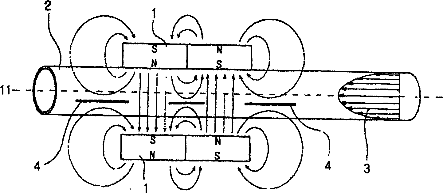
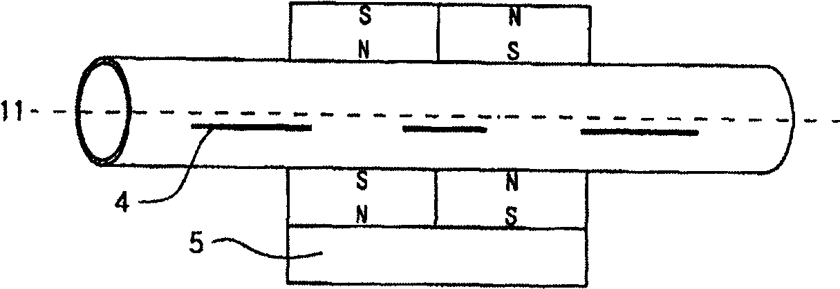
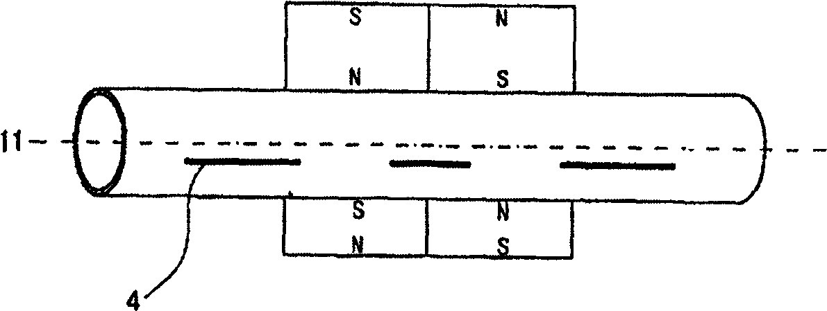
The invention relates to a liquid or gas magnetization device, which comprises a pair of magnets arranged opposite to each other to provide magnetic field energy to the liquid or gas in the liquid or gas pipeline, and the pair of magnets are arranged on the outside of the liquid or gas pipeline (2) , and the magnetic field boundary position of each magnet deviates from the central axis (11) of the liquid or gas pipeline.

Description

technical field [0001] The invention relates to a magnetizing device for liquids or gases. Background technique [0002] Recently, the technology of atomizing and activating liquid or gas particles to improve combustion efficiency has been in progress. This technology is to set magnets on the outer wall of the liquid or gas pipeline connected to the boiler or automobile engine to provide fuel. And use the magnetic field of the magnet to act on the liquid and gas. For example, Korean Laid-Open Patent No. 1997-70514 or Japanese Patent Laid-Open No. 59-176504 discloses a fuel reduction device in which a plurality of magnets with the same magnetic poles are adjacently arranged around the surface of the fuel pipe. However, this invention has problems that the magnetic force is easily exhausted and the lifetime of the magnet is shortened because the repulsive force generated by the arrangement of the same magnetic poles adjacent to each other continuously acts on the magnet. The...

Claims


Application Information

Patent Timeline
Patent Type & Authority Patents(China)
IPC IPC(8): F02M27/04
CPCF02M27/045
Inventor 黄桢烈陈琼爱
Owner 黄桢烈
Learn More