Control system and control method applied to hydraulic variable valves

A control system and variable technology, applied in the direction of valve device, machine/engine, mechanical equipment, etc., can solve the problems of engine output increase and disadvantage, achieve the effect of reducing friction, reducing cost and improving fuel mileage

Active Publication Date: 2020-04-07
HYUNDAI MOTOR CO LTD +1
View PDF8 Cites 2 Cited by
  • Summary
  • Abstract
  • Description
  • Claims
  • Application Information

AI Technical Summary

Problems solved by technology

In the case of a typical engine, once valve overlap is set, the set valve overlap is always used throughout the engine speed range, we have found that this can be disadvantageous in low or high engine speed ranges
[0010] Therefore, controlling the valve overlap according to the engine load may lead to an increase in engine output, and controlling the valve overlap according to the engine load in this way is a CVVT system

Method used


Image

  • Control system and control method applied to hydraulic variable valves
  • Control system and control method applied to hydraulic variable valves
  • Control system and control method applied to hydraulic variable valves

Examples


Embodiment Construction

[0038] The following description is merely exemplary in nature and is not intended to limit the disclosure, application or uses. It should be understood that throughout the drawings, corresponding reference numerals indicate like or corresponding parts and features.

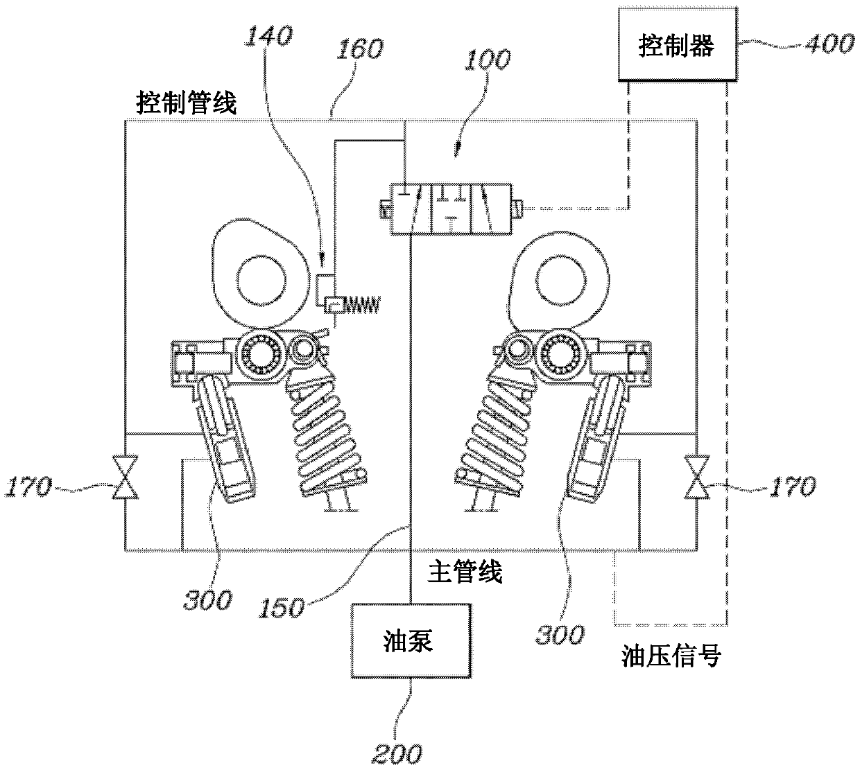
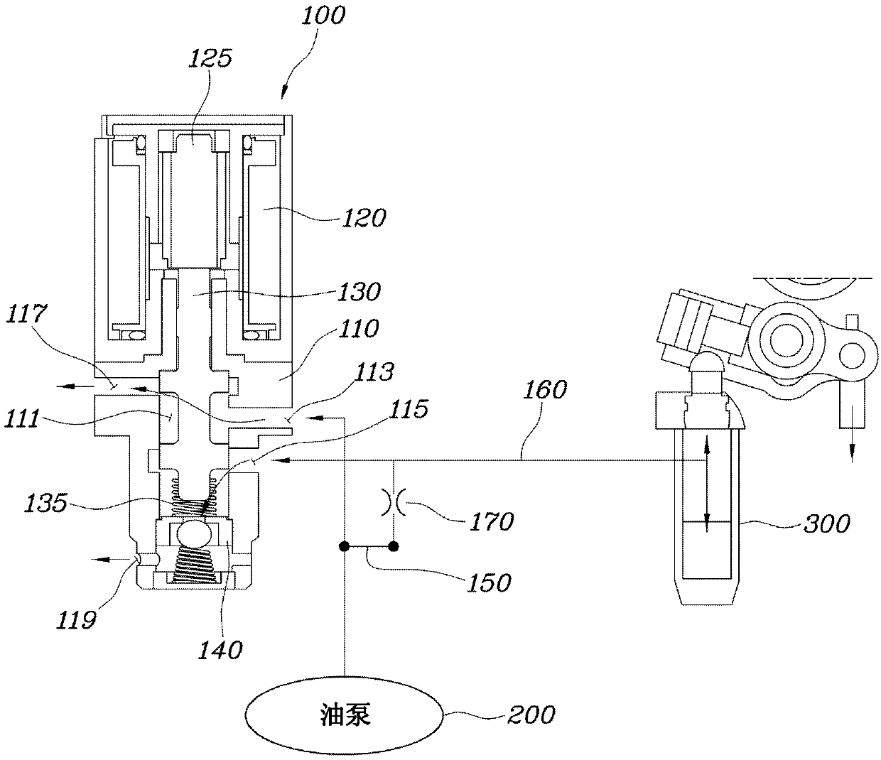
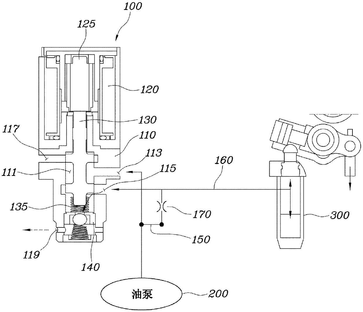
[0039] figure 1 is a block diagram schematically showing a control system for a hydraulically variable valve according to one form of the present disclosure, and Figure 2 to Figure 4 is a view showing oil flow and operation according to each control mode of the control system for a hydraulic variable valve according to the present disclosure.

[0040] refer to Figure 1 to Figure 4 , the control system for a hydraulic variable valve according to the present disclosure may include: an oil control valve (OCV) 100 configured with: a housing 110 in which a flow passage 111 is defined, provided on an outer peripheral surface of the housing 110 and The main port 113 that allows the flow passage 111 and the oil pump...


PUM


Abstract

The invention discloses a control system and a control method applied to hydraulic variable valves and relates to a control system applied to hydraulic variable valves. The control system comprises anOCV (Oil Control Valve), a main pipeline, a control pipeline, an orifice and a controller, wherein the OCV is provided with a shell and also comprises a flowing channel, a main port, a first discharging port, a second discharging port, a valve element and a safety valve which are limited in the shell; the main pipeline is connected with the main port and an oil pump; the control pipeline is usedfor connecting the control port and a clearance adjuster; the orifice is formed between the main pipeline and the control pipeline; and the controller is used for controlling the OCV to allow at leastone of a combination composed of the main port and the first discharging port, a combination composed of the control port and the second discharging port and a combination composed of the main port and the control port to be communicated with each other.

Description

technical field [0001] The present disclosure relates to a control system and a control method for a hydraulically variable valve. Background technique [0002] The statements in this section are intended merely to provide background information related to the present disclosure and may not constitute prior art. [0003] An internal combustion engine is an engine that generates power by receiving fuel and air from outside the engine and burning the fuel and air in a combustion chamber. The internal combustion engine generally has an intake valve through which fuel and air are drawn into the combustion chamber and an exhaust valve through which combustion gases are exhausted from the combustion chamber, wherein the intake valve and the exhaust valve are configured to rotate with the crankshaft. The rotation of the rotating camshaft opens and closes. [0004] In order to increase the efficiency of the engine, the timing of opening and closing of the valves may be varied depe...

Claims


Application Information

Patent Timeline
Patent Type & Authority Applications(China)
IPC IPC(8): F01L1/344
CPCF01L1/3442F01L2001/3443
Inventor 崔命植
Owner HYUNDAI MOTOR CO LTD
Why Eureka
Try Eureka