Drawing figures in computer-based drawing applications

a drawing application and computer-based technology, applied in the field of computer graphics, can solve the problems of inability to automatically associate lines with any of the target regions, and inability to use animation correctly

Active Publication Date: 2013-07-16
DISNEY ENTERPRISES INC
View PDF36 Cites 4 Cited by
  • Summary
  • Abstract
  • Description
  • Claims
  • Application Information

AI Technical Summary

Benefits of technology

[0010]One advantage of the disclosed techniques is that a user is not required to draw entirely within a target region of the graphical object template to associate a pen stroke with the target region. Every graphics object drawn or placed in the digital canvas is associated with one of the target regions based on the proximity scores associated with...

Problems solved by technology

One drawback to using a template in conventional drawing applications is that if the user draws lines outside of the defined target regions, such as the ears, neck, and tail of an animal template, then those lines may not be automatically associated with any of the target regions.
As a result, any functionality included in the drawing application based on the association with a target region may be broken.
Therefore, when the drawing application generates an animation that moves the ear target region, the user's ear may not move in a corresponding fashion with the ear targe...

Method used


Image

  • Drawing figures in computer-based drawing applications
  • Drawing figures in computer-based drawing applications
  • Drawing figures in computer-based drawing applications

Examples


Embodiment Construction

[0023]In the following description, numerous specific details are set forth to provide a more thorough understanding of the invention. However, it will be apparent to one of skill in the art that the invention may be practiced without one or more of these specific details. In other instances, well-known features have not been described in order to avoid obscuring the invention.

System Overview

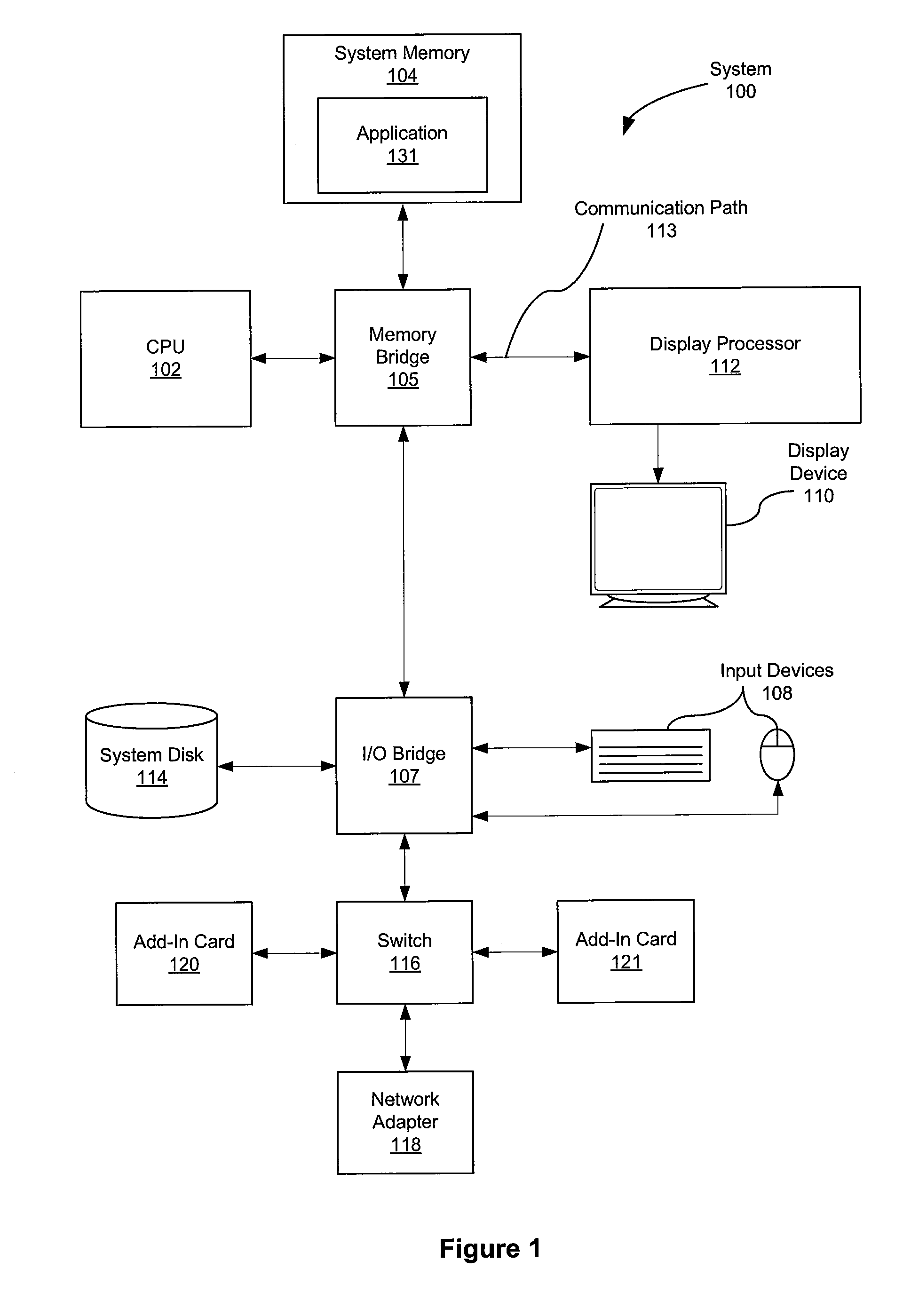
[0024]FIG. 1 is a block diagram of a system 100 configured to implement one or more aspects of the present invention. System 100 may be a computer workstation, personal computer, video game console, personal digital assistant, rendering engine, mobile phone, hand held device, smart phone, super-smart phone, or any other device suitable for practicing one or more embodiments of the present invention.

[0025]As shown, system 100 includes one or more processing units, such as central processing unit (CPU) 102, and a system memory 104 communicating via a bus path that may include a memory bridge 105. ...


PUM


Abstract

Techniques for associating a graphics object with one of a plurality of target regions of a graphical object template are disclosed. The graphics object is associated with one of the target regions based on the distance between the center of mass of the graphics object and the center of mass of the target region and the overlap amount of the graphics object with the target region. A pre-generated graphics object (stamp object) may also be automatically incorporated into one of the target regions based on the alignment of the minimum bounding box of the stamp object and the minimum bounding box of the target region.

Description

BACKGROUND OF THE INVENTION[0001]1. Field of the Invention[0002]Embodiments of the present invention relate generally to computer graphics and, more specifically, to drawing figures in computer-based drawing applications.[0003]2. Description of the Related Art[0004]Computer-based drawing applications, such as Microsoft Paint and Adobe Photoshop, have been developed to enable users (both children and adults) to draw directly on a digital canvas using various tools, such as a digital pen or digital brushes. In order to help users with limited drawing skills, some drawing applications implement templates that depict different types of real-life objects, such as airplanes, horses, dogs, and the like. When using such a template, a user draws directly over the template regions such that the resulting drawing reflects the basic shape of the depicted object. Some drawing applications may even create animations from the resulting drawing, moving the graphics drawn in the different template r...

Claims


Application Information

Patent Timeline
IPC IPC(8): G09G5/00G06K9/00G06T11/20G06K9/36
CPCG06T11/60
Inventor WARD, JEFFREY C.BALLAGH, JONATHANSTECKLEIN, TYSONMILNE, ROGER B.
Owner DISNEY ENTERPRISES INC
Why Eureka
Try Eureka