
Apparatus and method for multi-modal imaging in nonlinear raman microscopy

a multi-modal imaging and nonlinear raman technology, applied in the field of microscope apparatus, can solve the problems of inability to detect processes in biological and biochemical samples in real-time in a sufficiently precise manner, the detection radiation has the same wavelength and polarization, and the detection of the sought-after signal is more difficult, so as to achieve high chemical precision

Active Publication Date: 2013-07-16
LEICA MICROSYSTEMS CMS GMBH
View PDF11 Cites 2 Cited by
  • Summary
  • Abstract
  • Description
  • Claims
  • Application Information

AI Technical Summary

Benefits of technology

[0008]It is the object of the invention to specify a method and an apparatus for the microscopic examination of an object, which enable that fast-running microscopic processes are resolved with high chemical precision and displayed.
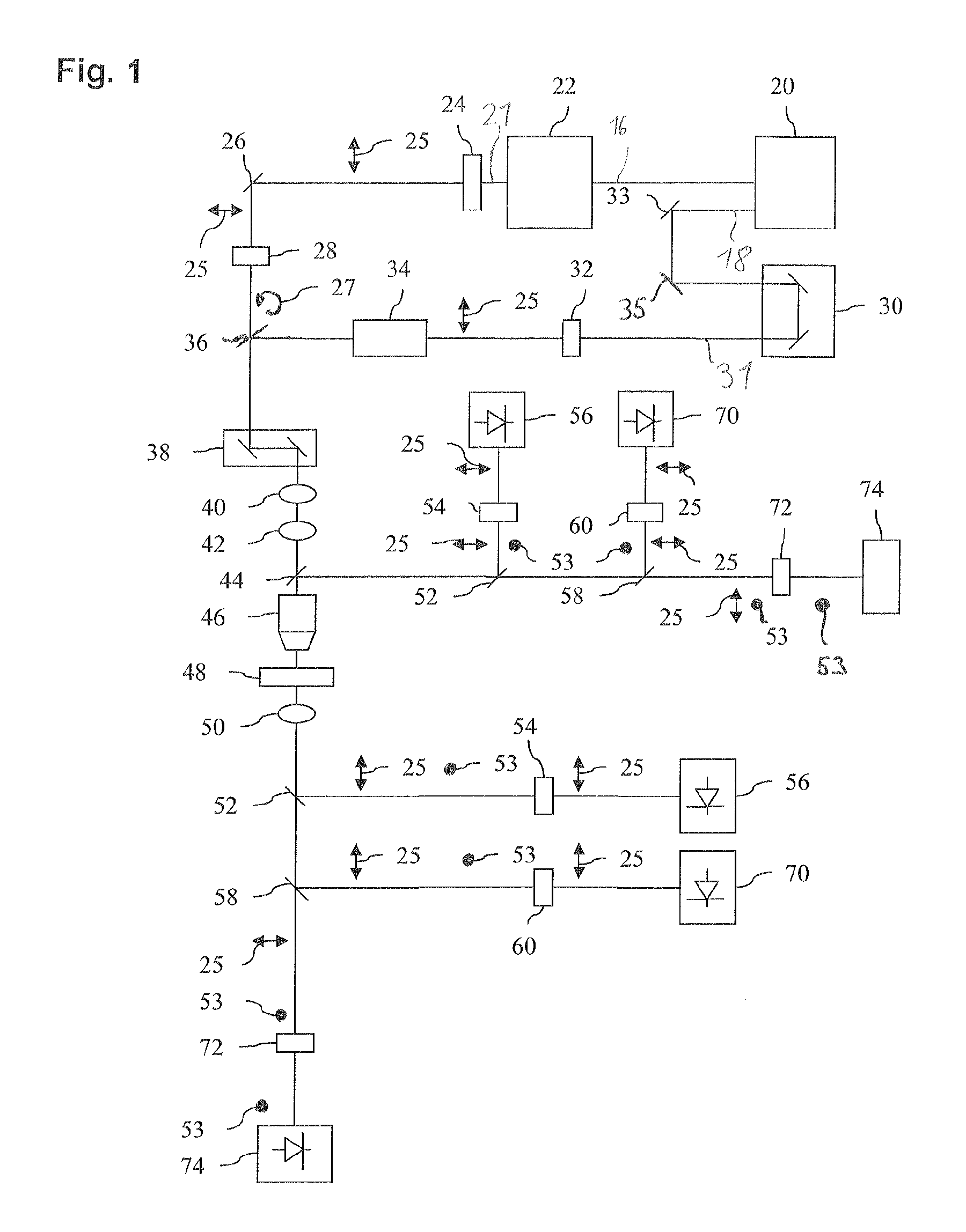
[0011]The detection of two distinct nonlinear Raman effects with one single apparatus enables, on the one hand, to precisely display fast-running microscopic processes and, on the other hand, to resolve the structures involved in these processes with high precision. The first illumination light beam is characterized by its circular polarization, and the second illumination light beam is characterized by its linear polarization and its modulation capability. The light source preferably comprises one or two light-generating single devices, for example one or two laser devices.
[0016]The precision in the examination of the object can be increased further in that the components are arranged such that the detection beams emitted in forward direction with respect to the illumination light beams and / or the detection beams emitted in reverse direction are detected.

Problems solved by technology

This technique is, however, too slow to detect processes in the biological and biochemical samples in real-time in a sufficiently precise manner.
One problem with these techniques is that the exciting radiation and the detection radiation have the same wavelength and polarization.
Thus, for the detection signal there results a very strong background signal that makes the detection of the sought-for signal more difficult.
Another disadvantage of CARS or CSRS is that the image obtained from the detection radiation contains chemically non-specific information as images obtained with CARS or CSRS also comprise non-resonant signals.
The RIKES signal is fast and chemically specific, however, compared to the other detection signals it is relatively weak.

Method used


Image

  • Apparatus and method for multi-modal imaging in nonlinear raman microscopy
  • Apparatus and method for multi-modal imaging in nonlinear raman microscopy
  • Apparatus and method for multi-modal imaging in nonlinear raman microscopy

Examples


first embodiment

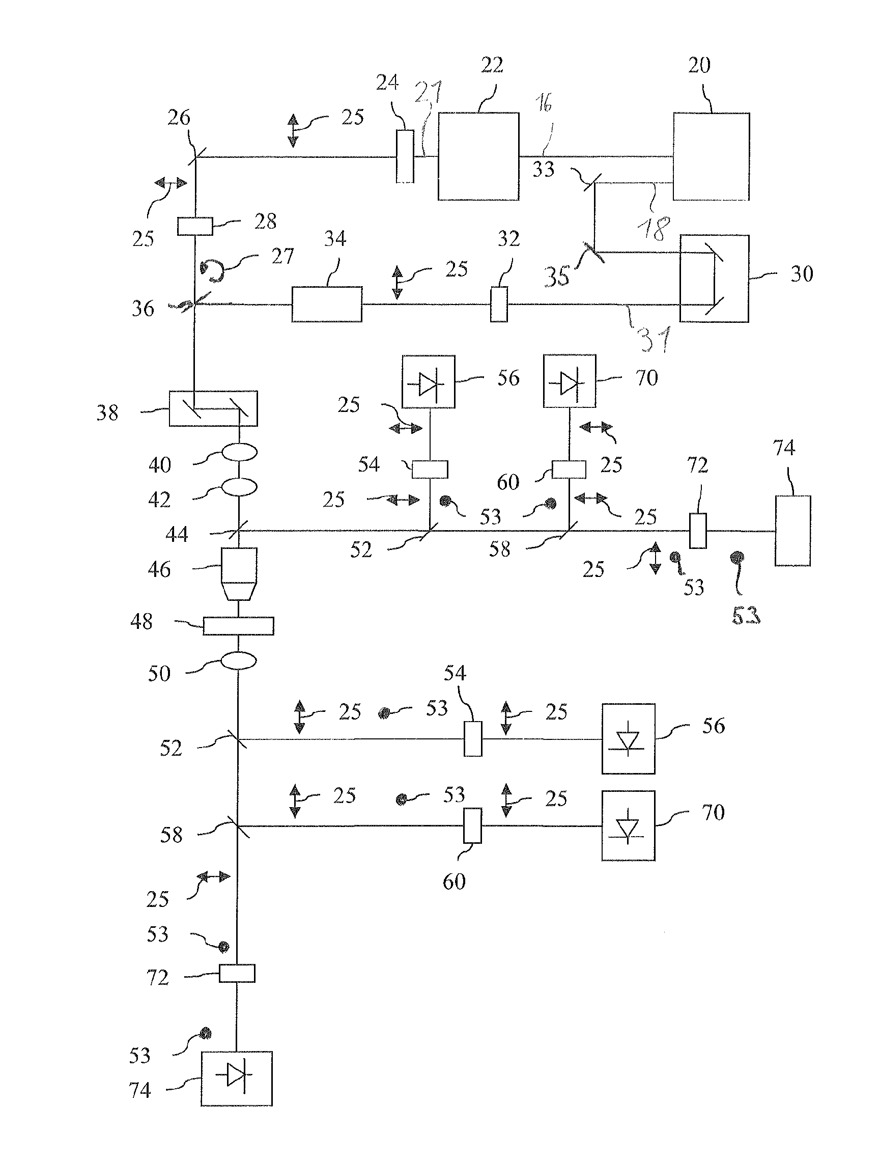
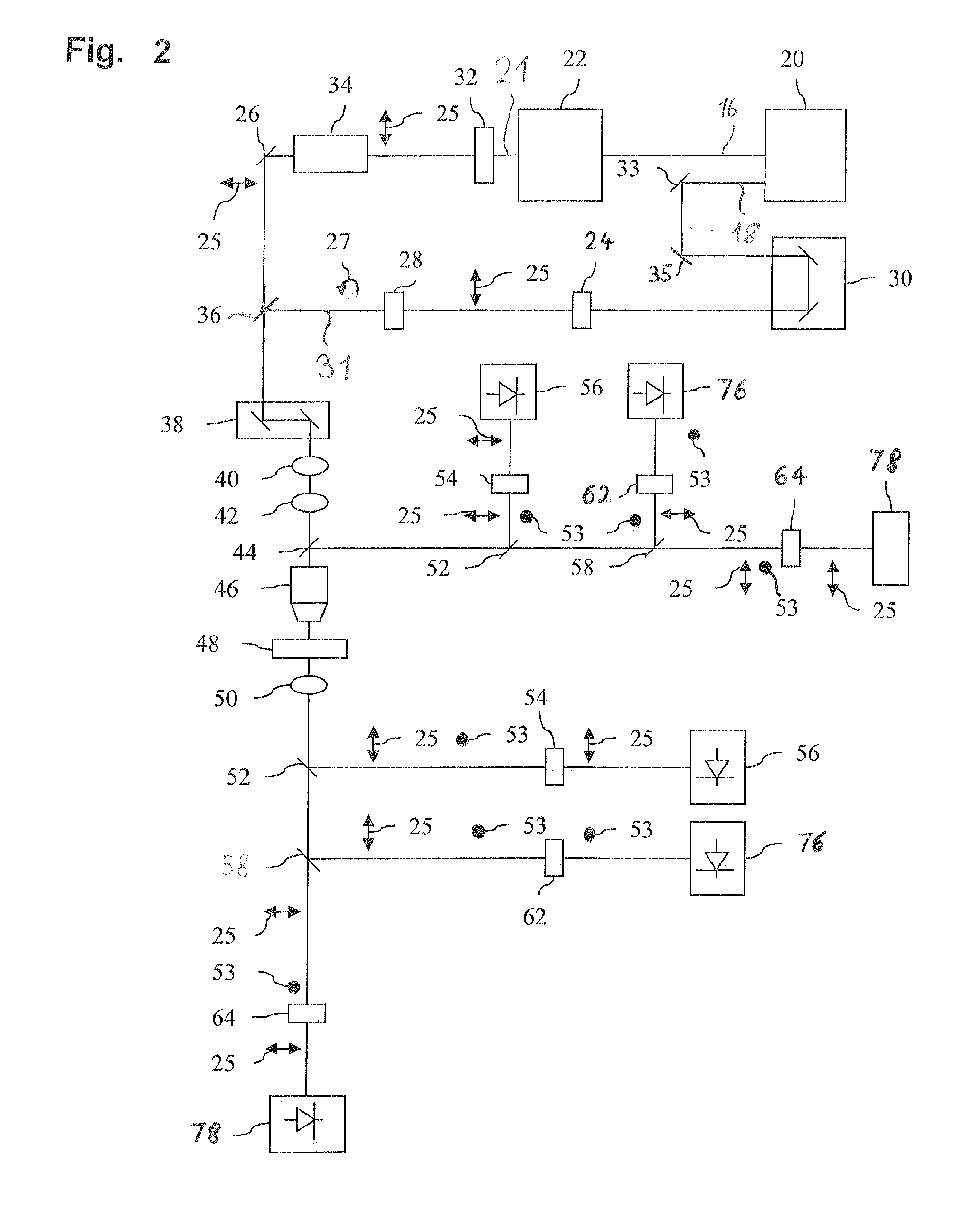
[0030]The detection light beams emanating from the sample 48 pass in forward direction via the condenser 50 and in reverse direction via the beam splitter 44 to the wavelength-selective elements 52, 58 and the detectors 56, 76, 78. The first wavelength-selective element 52 and the elements arranged downstream thereof such as the third polarization filter 54 and the first detector 56 as well as the second wavelength-selective element 58 correspond to the elements of the first embodiment identified with the same reference signs.

[0031]In contrast to the first embodiment, however, the radiation of the second wavelength range of the detection light beam is deflected to a sixth polarization filter 62 that s-polarizes the radiation of the second wavelength range and is then deflected to a fourth detector 76 that detects the Raman-induced Kerr effect. The fourth detector 76 preferably comprises a photomultiplier tube which is sensitive in the near infrared. In addition, the portion of the d...

second embodiment

[0032]During operation of the microscope the Stokes laser beam 31 with the fixed wavelength of 1064 nm is circularly polarized, and the pump laser beam 21 can be modulated. In a first step, for detecting fast-running processes in the sample 48, the pump laser beam 21 is not modulated, and with the aid of the first wavelength-selective element 52 radiation of the first wavelength range of the detection light beam is p-polarized and directed onto the first detector 56. Preferably at the same time, radiation of the second wavelength range of the detection light beam is s-polarized with the aid of the sixth polarization filter 62 and directed onto the fourth detector 76, the fourth detector 76 being sensitive at least in the second wavelength range and detecting the RIKES signal at wavelengths of the pump laser radiation.

[0033]In a second step, the pump laser beam 21 is modulated with the aid of the modulator 34. Radiation of the third wavelength range of the detection light beam is p-...


PUM


Abstract

An apparatus for the microscopic examination of an object has an illumination system which generates a first illumination light beam and a second illumination light beam. A first polarization filter (28) circularly polarizes the first illumination light beam. A second polarization filter (32) linearly polarizes the second illumination light beam. A modulator (34) allows a modulation of the polarized second illumination light beam. An excitation optical system directs the two illumination light beams onto an object. A detection optical system directs detection light beams emanating from the object onto at least two detector units, a first detector unit detecting a first nonlinear Raman effect and a second detector unit detecting a second nonlinear Raman effect.

Description

CROSS-REFERENCE TO RELATED APPLICATIONS[0001]This Application claims priority to German Patent Application No. DE 10 2010 015 964.6 filed on Mar. 15, 2010, that is incorporated herein by reference in its entirety.FIELD OF THE INVENTION[0002]The invention relates to an apparatus for the microscopic examination of an object. The apparatus has an illumination system and a first polarization filter. The illumination system generates a first illumination light beam and a second illumination light beam. The first polarization filter circularly polarizes the first illumination light beam.FBACKGROUND OF THE INVENTION[0003]Various Raman techniques are known to examine biological and biochemical samples. Linear Raman microscopy consists of irradiating a sample with a strong laser beam and detecting the frequency-modulated detection light emanating from the sample. This technique is, however, too slow to detect processes in the biological and biochemical samples in real-time in a sufficiently ...

Claims


Application Information

Patent Timeline
Patent Type & Authority Patents(United States)
IPC IPC(8): G01J3/44
CPCG01J3/02G01J3/0224G01J3/10G01J3/36G01J3/44G01N21/65G01N2021/653G01N2021/655
Inventor KRISHNAMACHARI, VISHNU VARDHAN
Owner LEICA MICROSYSTEMS CMS GMBH
Learn More