Terahertz-infrared ellipsometer system, and method of use

a technology of terahertz-infrared ellipsometer and polarimeter, which is applied in the direction of pyrometry using electric radation detectors, optical radiation measurement, instruments, etc., can solve the problems of not being able to provide synchrotron, and commercially available thz ellipsometers or polarimeters in the market place, so as to improve the purity of the polarization state exiting

Active Publication Date: 2013-07-16
J A WOOLLAM CO +1
View PDF58 Cites 0 Cited by
  • Summary
  • Abstract
  • Description
  • Claims
  • Application Information

AI Technical Summary

Benefits of technology

[0119]said detector;and comprises a method of its application in ellipsometer and polarimeter and the like systems. This is beneficial in that it eliminates the need to rotate an ellipsometer system Polarizer to rotate a polarization state provided by the source of electromagnetic radiation, optionally in combination with a polarization state generator. The odd bounce optical image rotating system is disclosed in U.S. Pat. No. 6,795,184 to Herzinger et al. As described in said 184 Patent said odd bounce serves optical image rotating system serves to rotate the azimuthal angle of a linearly, or partially linearly polarized, (ie. substantially polarized), beam of electromagnetic radiation without entering significant deviation or displacement of the propagation direction locus thereof, or significantly altering the polarization state thereof, (ie. it does not cause significant shifting of energy from a major intensity orthogonal component into the other orthogonal component, or the shifting of phase angle therebetween). The odd bounce optical image rotating system can be described as a sequence of an odd number of reflective elements oriented in a manner which causes an entering beam of electromagnetic radiation to reflect from a first thereof onto the second thereof and from the second thereof onto the third thereof etc. For a three (3) reflective element odd bounce optical image rotating element system, said three reflections cause a beam of electromagnetic radiation to emerge from the third reflective element with a rotated linear or partially linear polarization azimuthal angle and in a direction which is not significantly deviated or displaced from the locus of the input beam, even when the odd bounce optical image rotating system is caused to stepwise or continuously rotate about an axis coincident with the locus of the beam of electromagnetic radiation. The same is generally true for an odd bounce optical image rotating element system comprising any odd number, (eg. 3, 5, 7 etc.) of reflective elements. It is noted that the greater the number of reflective elements the more normal the angle of incidence a beam can make thereto, and higher angles of incidence cause less aberration effects. Also, where more than three reflection elements are present certain non-idealities caused by the reflection elements can be canceled by utilizing non-coincident coordinate systems for said reflections. A trade-off, however, is that the greater the number of reflective elements present, the more difficult it is to align the system to avoid said beam deviation and displacement.
[0269]It is also noted that the polarization state generator is characterized by a polarization state generator entry polarizer followed by said polarization state generator exit polarizer operates by the polarization state generator entry polarizer receiving an at least partially polarized beam of electromagnetic radiation from the source thereof and then passing it through said polarization state exit polarizer. Said polarization state generator entry polarizer serves to enable avoiding a condition wherein an effective azimuth of the at least partially polarized beam of electromagnetic radiation provided by the source thereof, and that of the polarization state generator exit polarizer present at essentially 90 degrees with respect to one another thereby preventing the at least partially polarized beam of electromagnetic radiation from progressing beyond the polarization state generator exit polarizer.

Problems solved by technology

To the Applicant's knowledge, there are no commercially available THz ellipsometers or polarimeters available in the market place.
While Synchrotrons have been used to provide THz frequency band electromagnetic radiation in ellipsometers, it is not remotely possible to provide a Synchrotron at every location whereat it is desired to practice THz ellipsometry.

Method used


Image

  • Terahertz-infrared ellipsometer system, and method of use
  • Terahertz-infrared ellipsometer system, and method of use
  • Terahertz-infrared ellipsometer system, and method of use

Examples


Embodiment Construction

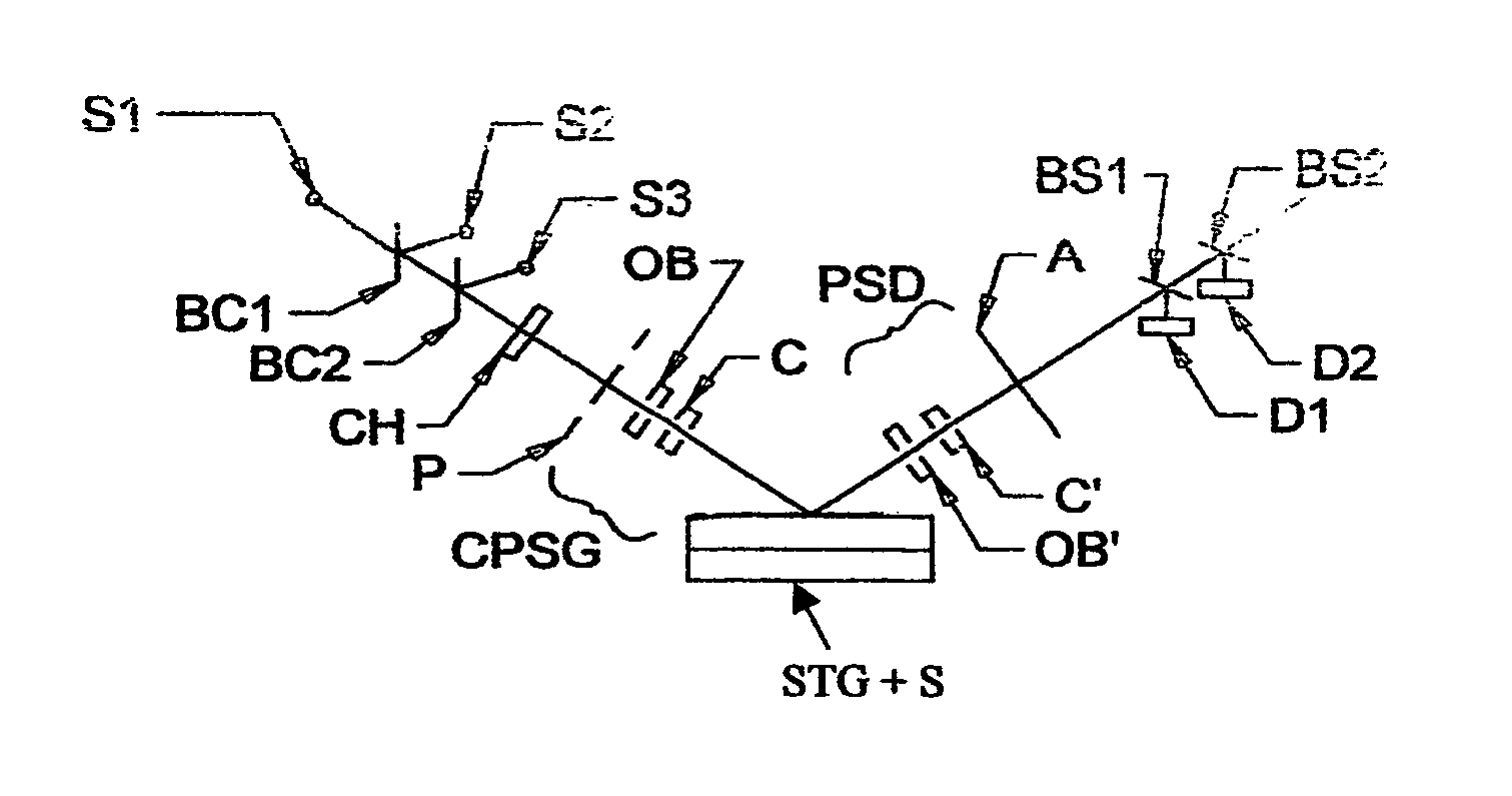
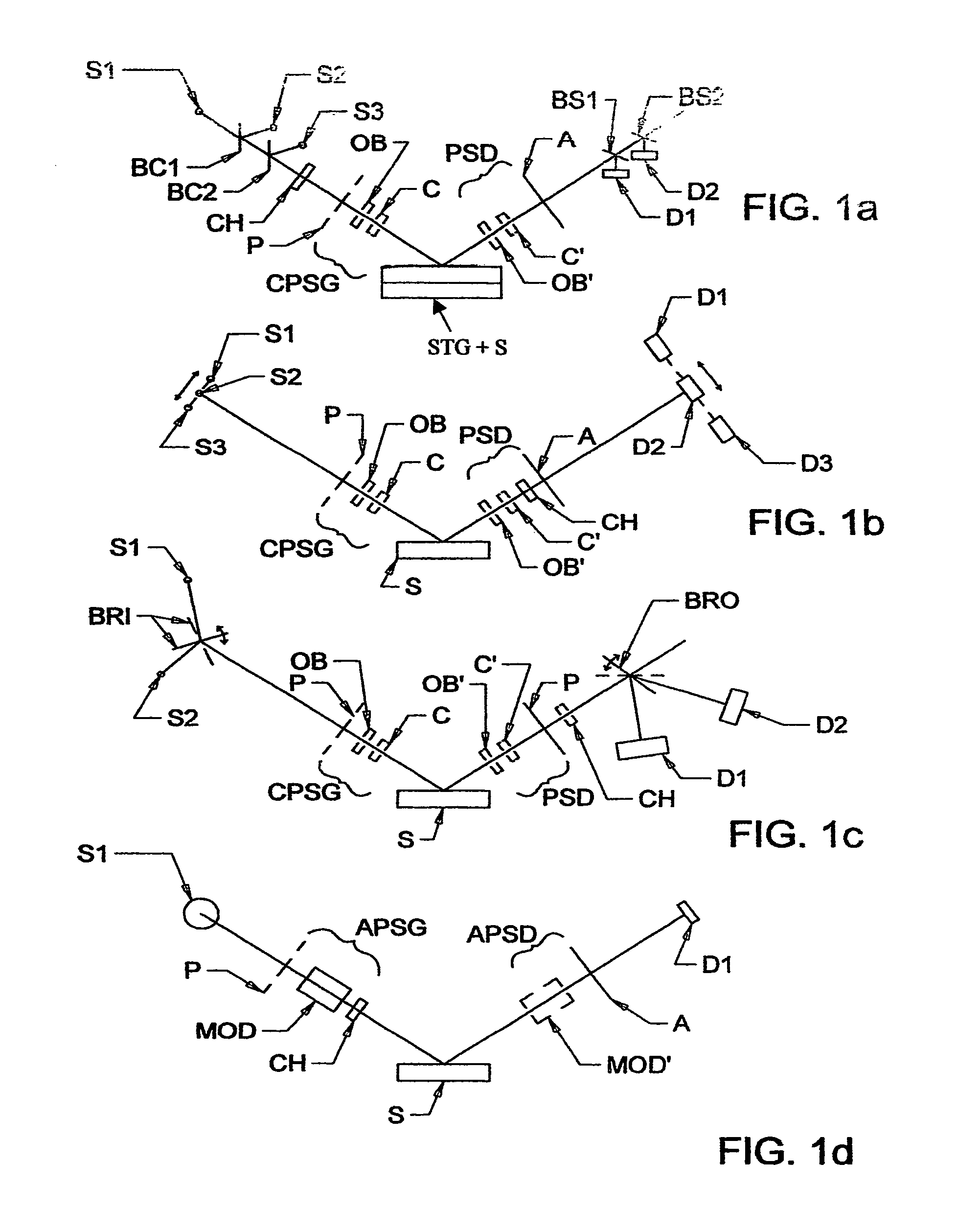
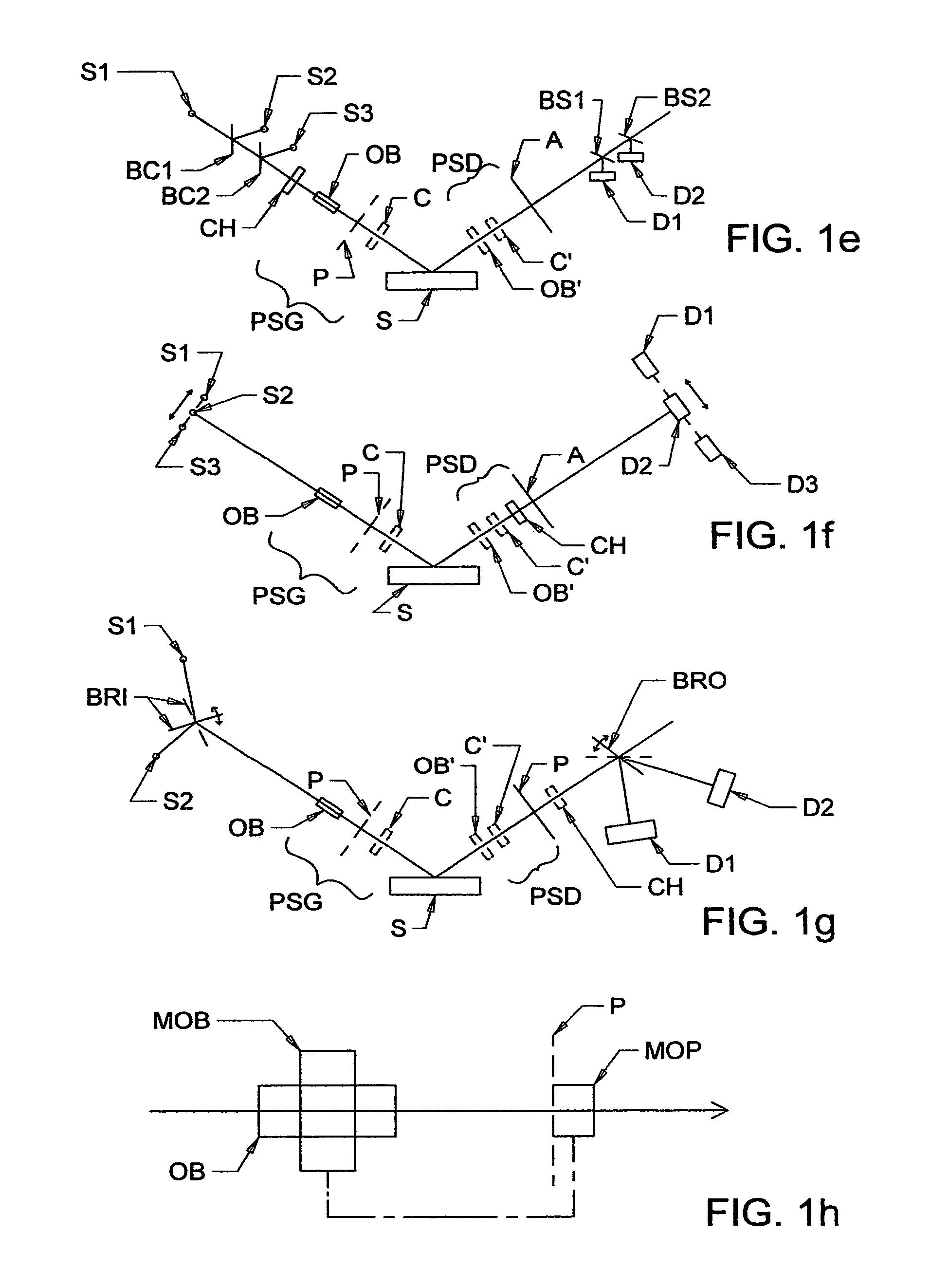
[0309]Turning now to the Drawings, FIGS. 1a, 1b and 1c show various approaches to providing a Present Invention System. FIG. 1a shows Three Sources (S1) (S2) S3), which can each be a backward wave oscillator or a Smith-Purcell cell or a free electron laser or a solid state device. Also demonstrated are Beam Combiners (BC1) (BC2) (BC3) which serve to direct electromagnetic radiation from Sources (S1) (S2) S3), respectively, toward a Sample (S), via optional Polarizer (P), (the natural source polarization can suffice), Odd Bounce Image Rotating System (OB) and Compensator (C). Said optional (P) (OB) (C) components are shown as typically, in combination, being termed a Conventional Polarization State Generator (CPSG) and are included to polarize a beam of electromagnetic radiation provided by a Source (S1) (S2) S3). As regards the Present Invention, however, it is possible that a selected Source (S1) (S2) S3) can provide a beam of electromagnetic radiation which is already polarized, t...


PUM


Abstract

A method of applying an ellipsometer or polarimeter system which operates in a frequency range between 300 GHz or lower and extending to higher than at least 1 Tera-hertz (THz), and preferably through the Infra-red (IR) range up to, and higher than 100 THz; wherein the ellipsometer or polarimeter system includes a source such as a backward wave oscillator, a Smith-Purcell cell, a free electron laser, an FTIR source or a solid state device; and a detector such as a Golay cell a bolometer or a solid state detector; and preferably includes at least one odd-bounce polarization state image rotating system and a polarizer, and at least one compensator and / or modulator, in addition to an analyzer.

Description

CROSS-REFERENCE TO OTHER APPLICATIONS[0001]This Application is a CIP of Ser. No. 12 / 456,791 Filed Jun. 23, 2009 and therevia Claims Benefit of Provisional Application Ser. No. 61 / 208,735 Filed Feb. 27, 2009, and further Claims Benefit of Provisional Application Ser. No. 61 / 281,905 Filed Nov. 22, 2009.STATEMENT OF FINANCIAL SUPPORT[0002]This invention which is subject in this application was developed in part under support provided by a Grant from the Army under Phase I ARMY STTR Contract No. W911NF-08-C-01121.[0003]The portion of this invention concerning the “odd bounce image rotation system and method of use” in this application was developed in part under support provided by a Grant from the National Science Foundation under Phase II SBIR Contract No. 9901510.[0004]The United States Government has certain rights in this invention.TECHNICAL FIELD[0005]The present invention relates to ellipsometer and polarimeter systems which comprise a source of electromagnetic radiation, a polar...

Claims


Application Information

Patent Timeline
Patent Type & Authority Patents(United States)
IPC IPC(8): G01J4/00
CPCG01N21/211G01N21/3581G01J5/20G01J5/42G01N2021/3595
Inventor HERZINGER, CRAIG M.SCHUBERT, MATHIAS M.HOFMANN, TINOLIPHARDT, MARTIN M.WOOLLAM, JOHN A.
Owner J A WOOLLAM CO
Why Eureka
Try Eureka