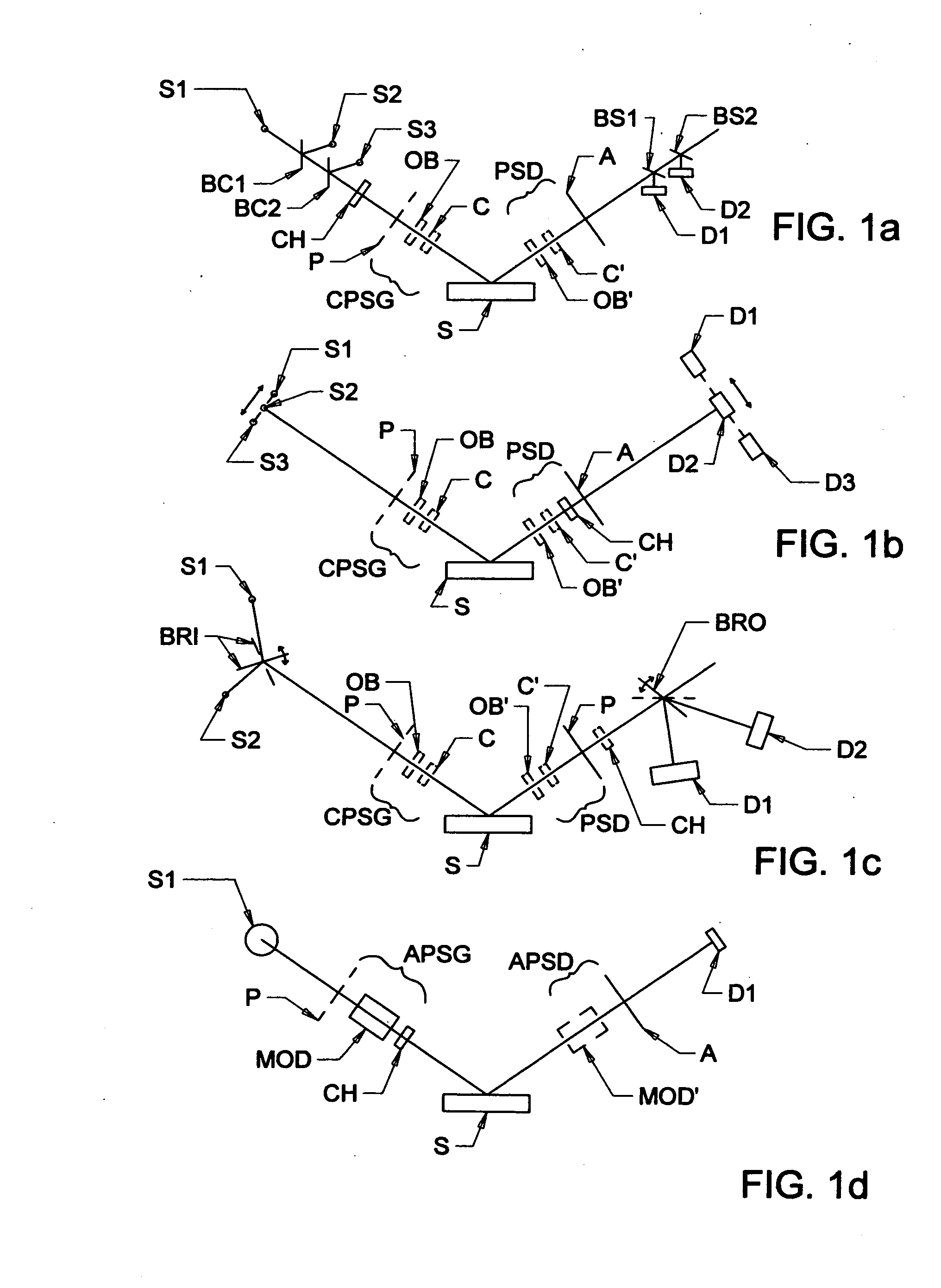
[0121]said detector;and comprises a method of its application in ellipsometer and polarimeter and the like systems. This is beneficial in that it eliminates the need to rotate an ellipsometer system
Polarizer to rotate a polarization state provided by the source of electromagnetic
radiation, optionally in combination with a polarization state generator. The odd bounce
optical image rotating system is disclosed in U.S. Pat. No. 6,795,184 to Herzinger et al. As described in said 184 patent said odd bounce serves
optical image rotating system serves to rotate the azimuthal angle of a linearly, or partially linearly polarized, (ie. substantially polarized), beam of electromagnetic
radiation without entering significant deviation or displacement of the propagation direction locus thereof, or significantly altering the polarization state thereof, (ie. it does not cause significant shifting of energy from a major intensity orthogonal component into the other orthogonal component, or the shifting of
phase angle therebetween). The odd bounce
optical image rotating system can be described as a sequence of an odd number of reflective elements oriented in a manner which causes an entering beam of electromagnetic
radiation to reflect from a first thereof onto the second thereof and from the second thereof onto the third thereof etc. For a three (3) reflective element odd bounce optical image rotating element system, said three reflections cause a beam of electromagnetic radiation to emerge from the third reflective element with a rotated linear or partially
linear polarization azimuthal angle and in a direction which is not significantly deviated or displaced from the locus of the input beam, even when the odd bounce optical image rotating system is caused to stepwise or continuously rotate about an axis coincident with the locus of the beam of electromagnetic radiation. The same is generally true for an odd bounce optical image rotating element system comprising any odd number, (eg. 3, 5, 7 etc.) of reflective elements. It is noted that the greater the number of reflective elements the more normal the
angle of incidence a beam can make thereto, and higher angles of incidence cause less aberration effects. Also, where more than three reflection elements are present certain non-idealities caused by the reflection elements can be canceled by utilizing non-coincident coordinate systems for said reflections. A trade-off, however, is that the greater the number of reflective elements present, the more difficult it is to align the system to avoid said beam deviation and displacement.
[0174]The benefit is that, especially in ellipsometer / polarimeter etc. systems which operate in the IR range of wavelengths and below, it can be difficult to cause rotation of a linear
polarizer, (or analyzer), without adversely causing deviation of a beam of electromagnetic radiation caused to pass therethrough, or causing mis-coordination of multiple elements thereof, (ie. multiple tipped wire linear
polarizer as described in U.S. Pat. No. 5,946,098). The present invention allows setting fixed substantially linear polarizer, and analyzer azimuthal orientations, and using the odd bounce optical image rotating element instead, to effect different electromagnetic beam azimuthal rotation orientations.
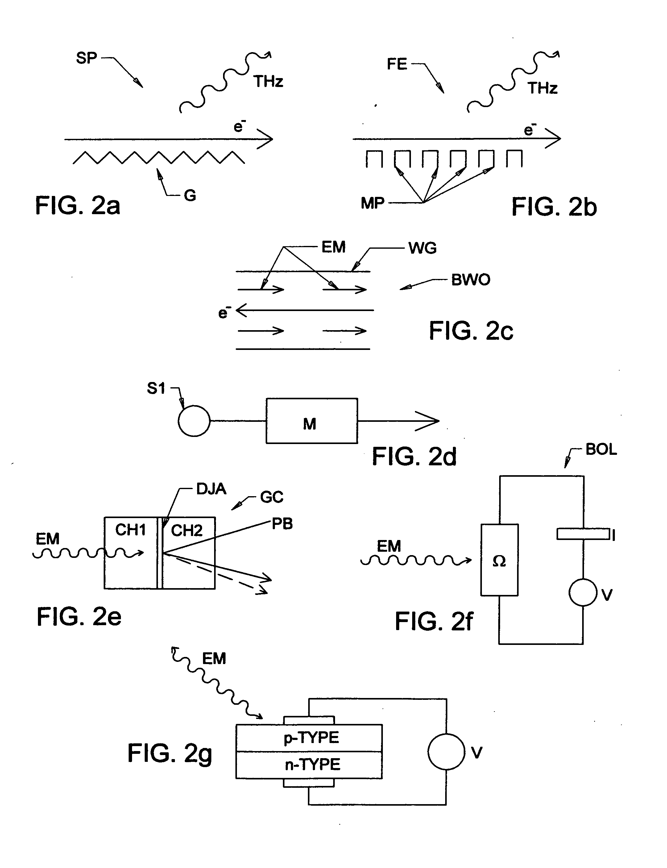
[0184]a
solid state source device;for each of the THz and IR ranges of operation, can provide different quality or, for instance, ellipsometric PSI or
DELTA results, as quantified by measured
Noise /
Signal ratios, and extent of
wavelength range. As regards the later point, it is noted that it can be advantageous to provide two THz sources which provide different
wavelength output and combine their outputs.
[0185]At the time of this submittal it is believed that a preferred embodiment makes use of a
backward wave oscillator (BWO) in combination with a multiplier that provides ×1, ×2 ×3 ×6 and ×9 capability, in functional combination with Golay
cell or
bolometer, provides good results in the range of from about 0.12-1.5 THz. Further, a conventional FTIR Source as used in a J.A. Woollam Co. IR-
VASE®, to provide 10-150 THz capability, has been shown capable of providing output down to about 1.0 Thz. This beneficially allows an overlap between the THz and IR sources between about 1.0 and 1.4 Thz, which can be used for
verification of results separately obtained using the THz and IR sources. In addition, it can be advantagous to cool a detector, (eg. by use of liquid helum), and to adjust beam
chopper rate, (eg. between about 12-50 Hz), differently for different source and detector combinations.

