Electrical connection box

a technology of electrical connection and box body, applied in the direction of coupling device connection, coupling device details, contact members penetrating/cutting insulation/cable strands, etc., to achieve the effect of improving the reliability of mechanical connection between the first and the second cassette block, preventing separation from each other

Active Publication Date: 2013-07-23
YAZAKI CORP
View PDF4 Cites 6 Cited by
  • Summary
  • Abstract
  • Description
  • Claims
  • Application Information

AI Technical Summary

Benefits of technology

[0014]In view of the above-described problem, an object of the present invention is to provide a downsized electrical connection box having improved mechanical connection reliability between the cassette blocks of the electrical connection box.
[0016]According to the present invention described above, the first and the second blocks can be coupled to each other without requiring the above-described mechanical connection structure of the conventional electrical connection box, thereby downsizing the electrical connection box. Also, according to the present invention, the number of electric components mounted to the first and the second blocks can be increased.
[0018]According to the present invention described above, the first and the second electric wires can be connected to each other without requiring the above-described electrical connection structure of the conventional electrical connection box, thereby further downsizing the electrical connection box.
[0020]According to the present invention described above, the first and the second blocks are firmly engaged with each other and are prevented from being separated from each other due to the vibratory movement of the moving vehicle. Thus, the reliability of the mechanical connection between the first and the second cassette blocks can be improved.

Problems solved by technology

However, there is a problem in the above-described conventional electrical connection box 101.
There is another problem in the conventional electrical connection box 101.

Method used


Image

  • Electrical connection box
  • Electrical connection box
  • Electrical connection box

Examples


Embodiment Construction

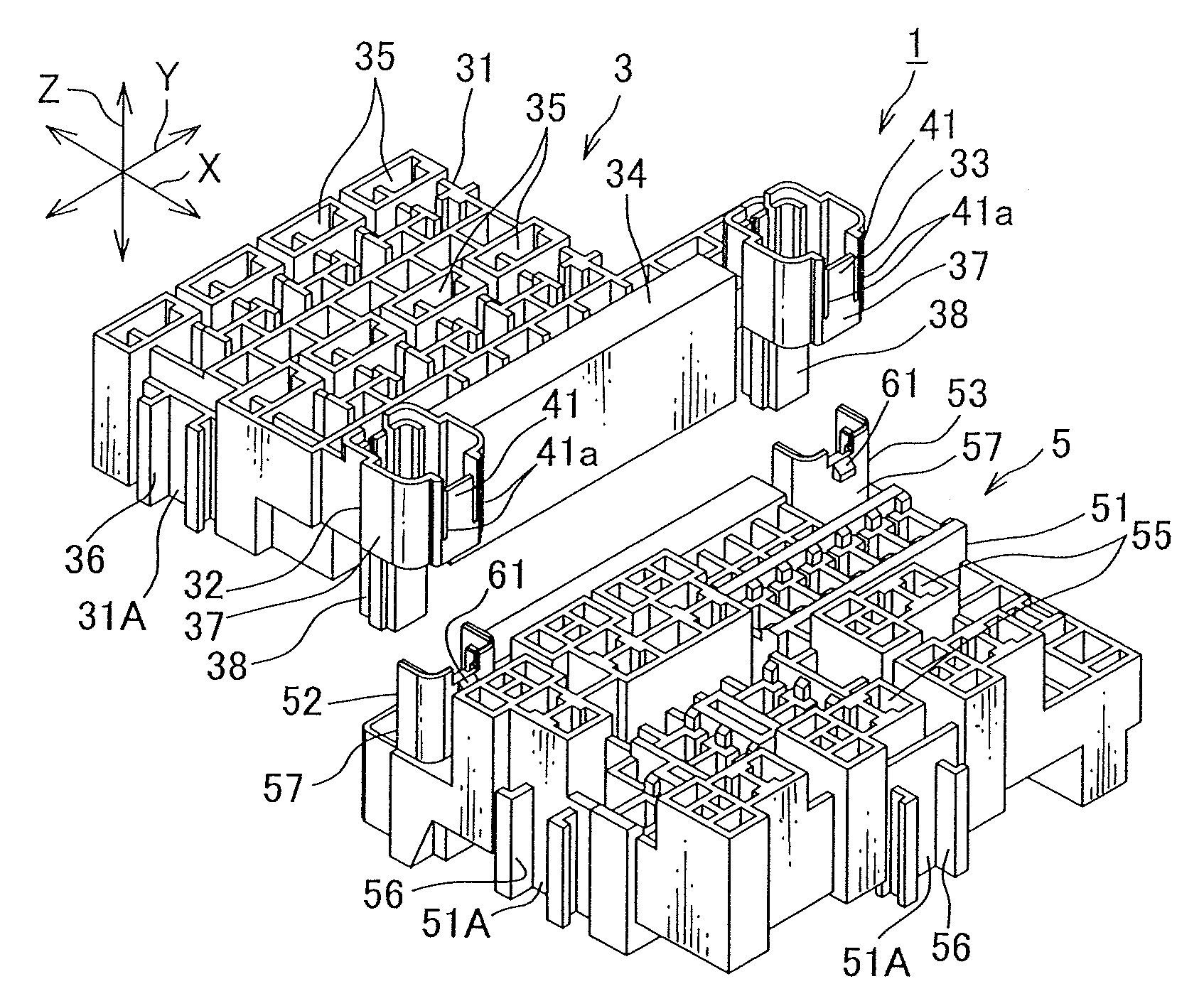
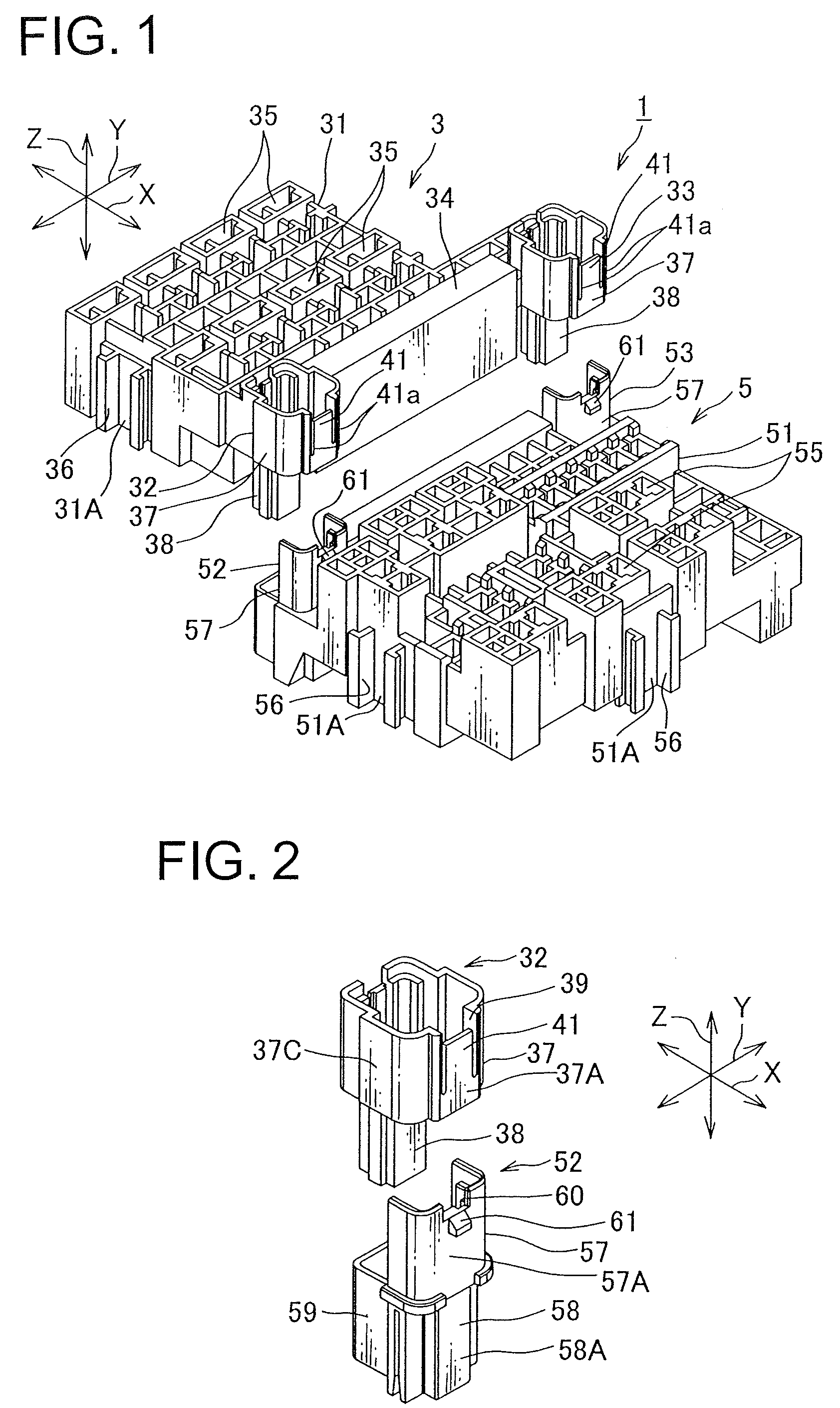
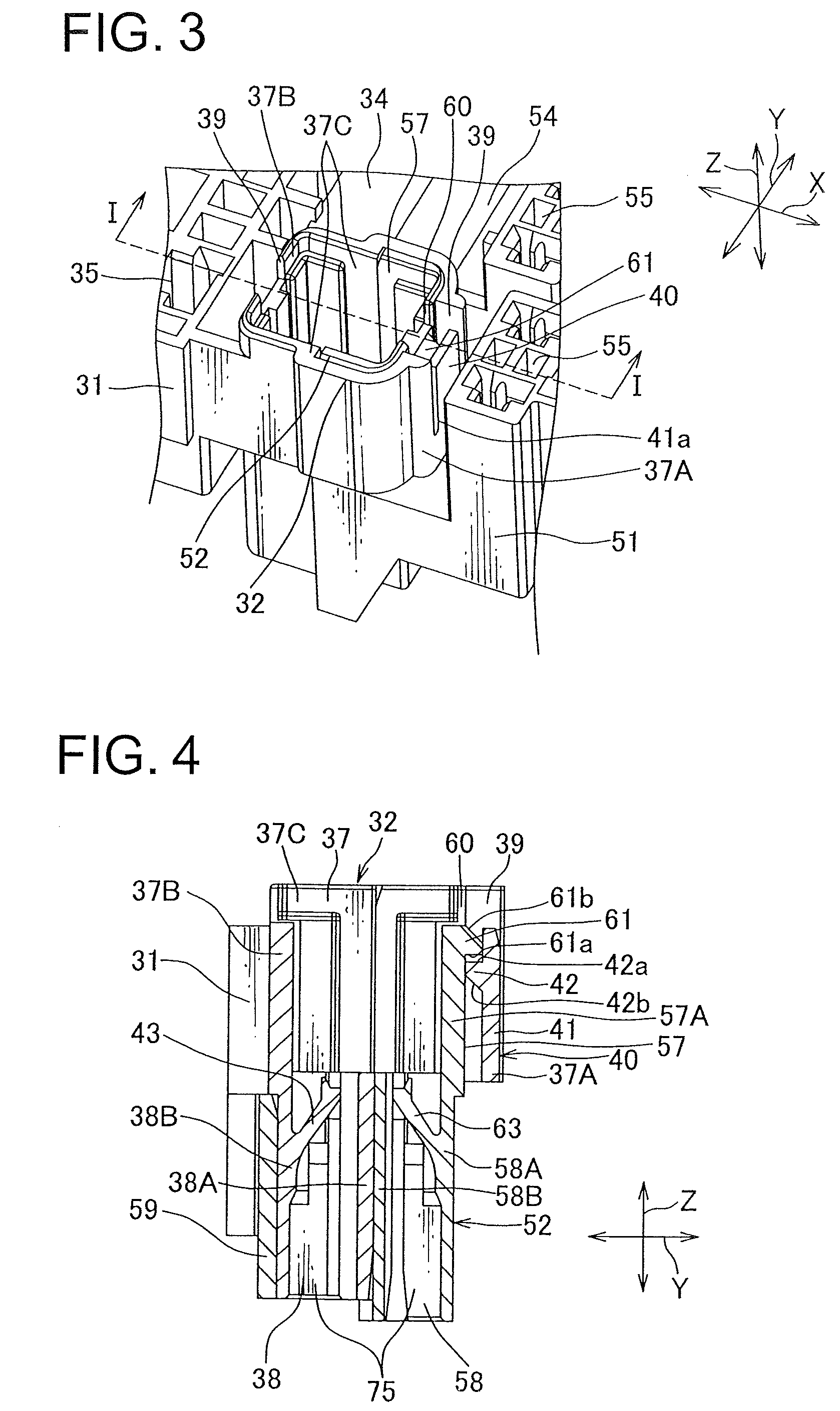
[0028]An electrical connection box according to one embodiment of the present invention is described below with reference to FIGS. 1 through 5.

[0029]An electrical connection box 1 according to the present invention is arranged to be mounted to an engine room of a motor vehicle to supply electrical power to various electric equipments mounted to the motor vehicle. The term electrical connection box used herein is broadly interpreted as a junction box, a fuse block or a relay box.

[0030]As shown in FIGS. 1 through 5, the electrical connection box 1 includes a plurality of electric components, a first cassette block 3 having a pair of first receiving portions 32, 33, a second cassette block 5 coupled to the first cassette block 3 and having a pair of second receiving portions 52, 53, a plurality of first electric wires wired at the first cassette block 3, a plurality of second electric wires wired at the second cassette block 5, a fuse 8 connected to the first and the second electric wi...


PUM


Abstract

There is provided a downsized electrical connection box in which the reliability of the mechanical connection between blocks provided in the electrical connection box is improved. The electrical connection box 1 includes a plurality of electric components, a first block 3 mounted with the electric components and a second block mounted with the electric components. The first block 3 includes a tubular-shaped first member32, 33 projecting towards the second block 5. The second block 5 includes a second member 52, 53 arranged to be slidably inserted into the first member. The first and the second blocks 3, 5 are coupled to each other by slidably inserting the second member 52, 53 into the first member 32, 33. At least one electric component 8 of the plurality of electric components is received inside the first and the second members 32, 52, 33, 53.

Description

CROSS REFERENCE TO RELATED APPLICATION[0001]The priority application Japanese Patent Application No. 2010-190794 upon which this patent application is based is hereby incorporated by reference.BACKGROUND OF THE INVENTION[0002]1. Field of the Invention[0003]The present invention relates generally to an electrical connection box to be mounted to an engine room of a motor vehicle.[0004]2. Description of the Related Art[0005]Various electric equipments are mounted to a motor vehicle as a moving body. In order to supply electric power to those electric equipments, an electrical connection box is mounted at suitable places in the vehicle between a power source and the electric equipments. Such electrical connection box is mounted with electric components such as a connector, a relay and a fuse.[0006]The term an electrical connection box used herein is also referred to as a junction block, a fuse block or a relay box.[0007]FIG. 6 is a perspective view of a conventional electrical connectio...

Claims


Application Information

Patent Timeline
Patent Type & Authority Patents(United States)
IPC IPC(8): H01R4/24
CPCH05K7/026
Inventor SATO, HISASHIYAMAMOTO, MASAKINAKAMURA, KAZUAKIHAGIWARA, MASAYUKI
Owner YAZAKI CORP
Why Eureka
Try Eureka