Sensor arrangement for determining at least one parameter of a fluid medium flowing through a channel structure

Active Publication Date: 2018-07-05
ROBERT BOSCH GMBH
View PDF13 Cites 3 Cited by
  • Summary
  • Abstract
  • Description
  • Claims
  • Application Information

AI Technical Summary

Benefits of technology

[0022]A basic idea of the present invention is the omission of the conventional main channel outlet, and a unification of the main channel with the measurement channel in the interior of the channel structure, as well as a displacement of the common outlet in the upstream direction. Through the omission of the lateral outlet and the positioning of the common outlet at the end face of the plug-in sensor, there results a nearly symmetrical configuration of inlet and outlet, resulting in lower sensitivity when there are changes of the incoming flow, in particular changes in the angle of incidence at the plug-in sensor. In addition, the signal noise is reduced, because it is no longer the case that two pressures, in some circumstances fluctuating with opposite phases, act at a main channel and a bypass channel; rather, only one pressure level acts at the common outlet. The migration of the stagnation point shown in FIG. 6, and the degree of the temporal change of the ratio of the mass flow going through both channel parts, i

Problems solved by technology

Besides the goal of reducing a pressure drop at the hot-film air mass sensor overall through suitable flow-related designs, one of the main challenges is to further improve the signal quality and the robustness of such devices against contamination by oil and water droplets, as well as rust, dust, and other solid particles.
After the flow around the sensor bearer, an unstable wake for

Method used


Image

  • Sensor arrangement for determining at least one parameter of a fluid medium flowing through a channel structure
  • Sensor arrangement for determining at least one parameter of a fluid medium flowing through a channel structure
  • Sensor arrangement for determining at least one parameter of a fluid medium flowing through a channel structure

Examples


Embodiment Construction

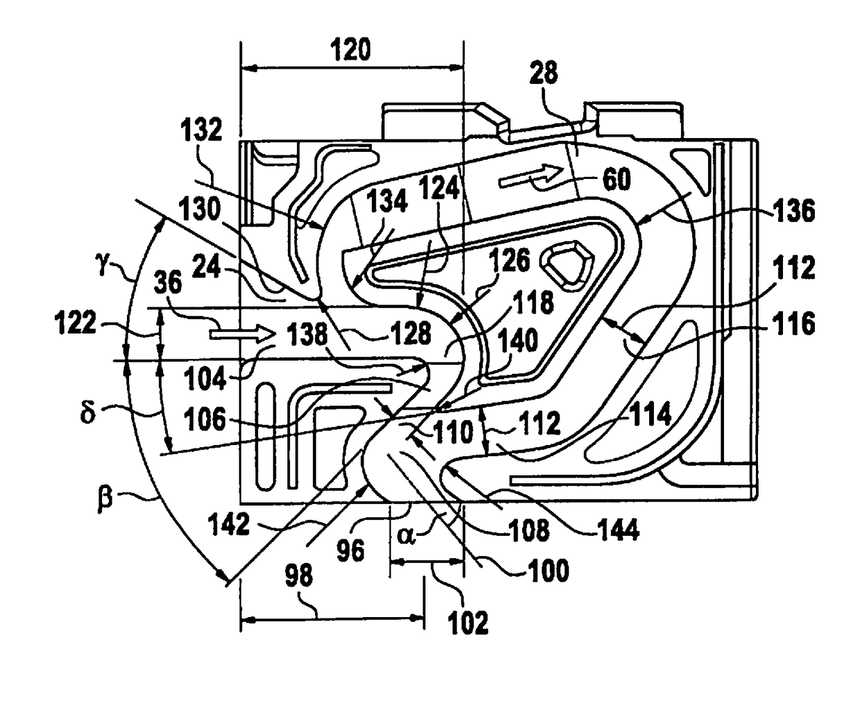
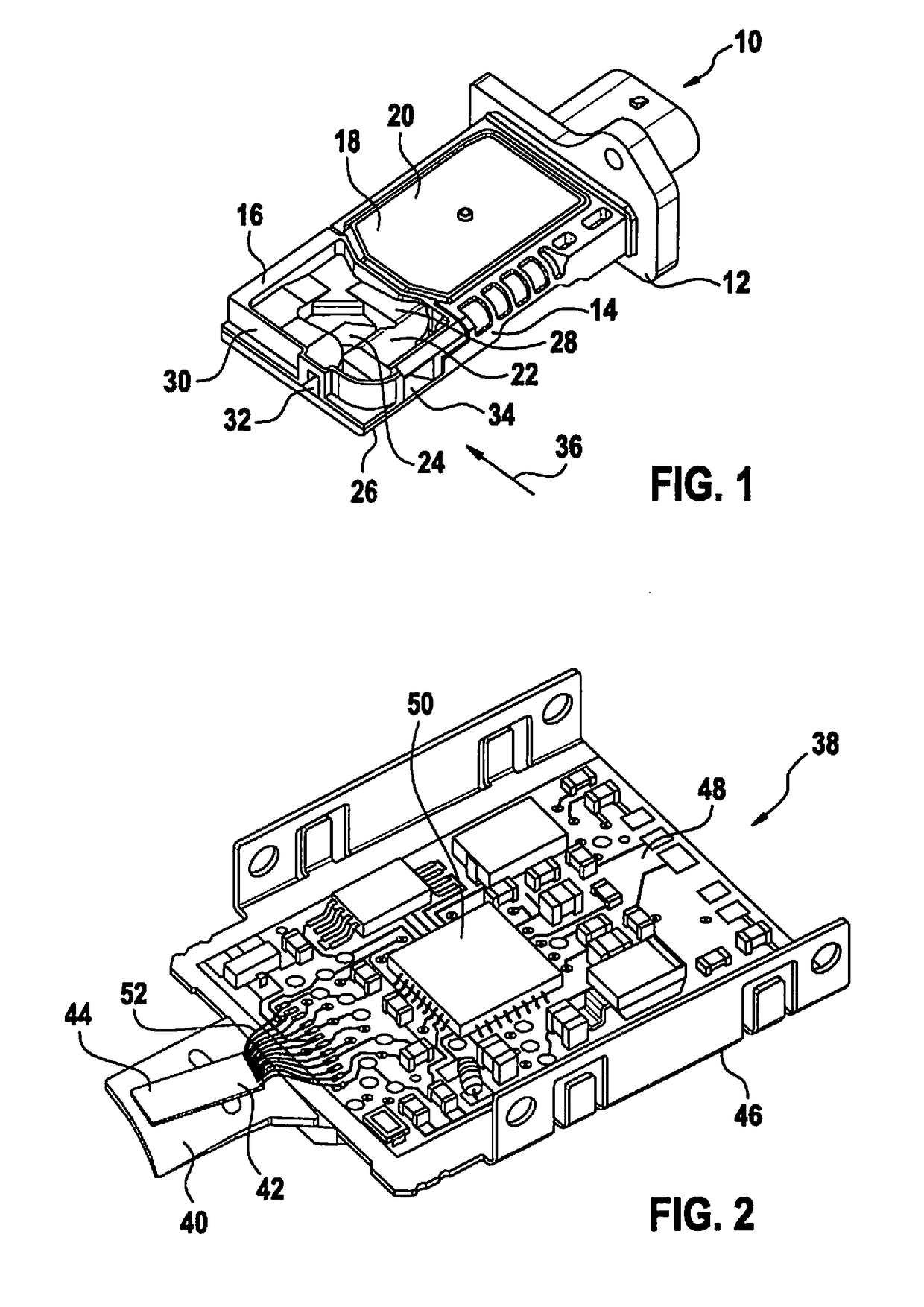
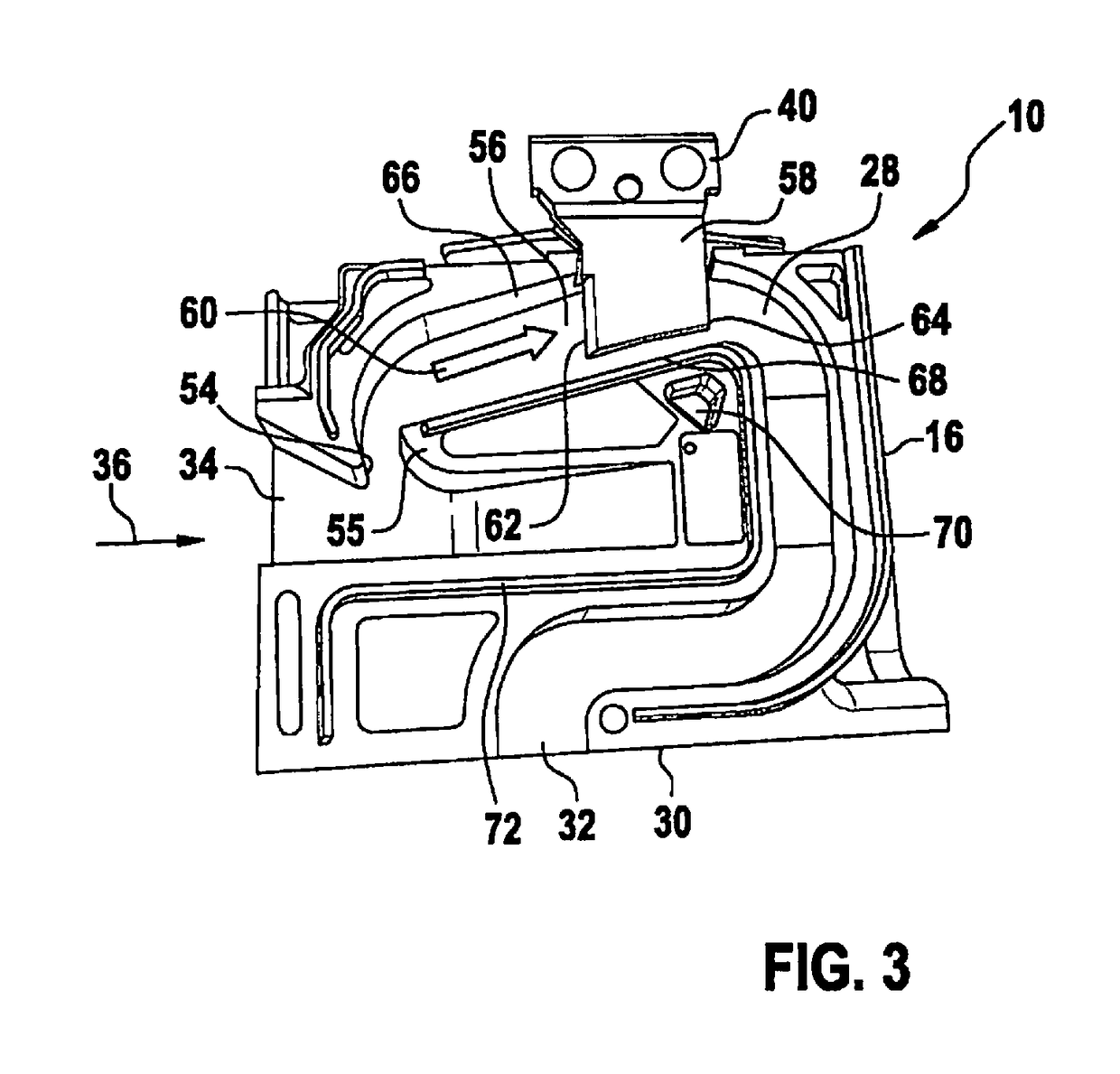
[0032]FIG. 1 shows a perspective view of a sensor system 10 for determining a parameter of a fluid medium. Sensor system 10 is fashioned as a hot-film air mass sensor, and includes a sensor housing 12 fashioned as a plug-in sensor, which can for example be inserted into a flow tube, in particular an intake system of an internal combustion engine. Sensor housing 12 has a housing body 14, a measurement channel cover 16, an electronics compartment 18, and an electronics compartment cover 20 for sealing electronics compartment 18. A channel structure 22 is fashioned in measurement channel cover 16. Channel structure 22 has a main channel 24 that discharges in a main channel outlet 25 (FIG. 6) on lower side 26 (relative to the depiction in FIG. 1) of sensor housing 12, and a bypass or measurement channel 28 branching off from main channel 24, which bypass channel discharges into a bypass or measurement channel outlet 32 situated in an end face 30 of sensor housing 12. A representative qu...


PUM


Abstract

A sensor system is provided for determining at least one parameter of a fluid medium flowing through a channel structure, e.g., an air mass flow of an internal combustion engine. The sensor system has a sensor housing, e.g., a plug-in sensor that is introduced or can be introduced into a flow tube, in which the channel structure is formed, and at least one sensor chip, situated in the channel structure, for determining the parameter of the fluid medium. The sensor housing has an inlet into the channel structure, oriented opposite a main direction of flow of the fluid medium, and an outlet from the channel structure. The channel structure includes a main channel and a measurement channel. The measurement channel branches off from the main channel. The sensor chip is in the measurement channel. The main channel and the measurement channel discharge together into the outlet from the channel structure.

Description

BACKGROUND INFORMATION[0001]Numerous conventional methods and devices are available for determining a flow property of fluid media, i.e., liquids or gases. The flow properties can be any physical and / or chemically measurable properties that qualify or quantify a flow of the fluid medium. In particular, the property can be a flow speed and / or a mass flow and / or a volume flow.[0002]Below, the present invention is described in particular with reference to so-called hot-film air mass sensors, as described for example in Konrad Reif (pub.): Sensoren im Kraftfahrzeug (Sensors in the motor vehicle), 1st ed., 2010, pp. 146-148. Such hot-film air mass sensors are based, as a rule, on a sensor chip, in particular a silicon sensor chip, having a sensor membrane as measurement surface or sensor region over which the fluid medium can flow. Generally, the sensor chip includes at least one heating element as well as at least two temperature sensors that are for example situated on the measurement ...

Claims


Application Information

Patent Timeline
IPC IPC(8): G01F1/684F02D41/18G01F1/688
CPCG01F1/6842F02D41/187G01F1/6845G01F1/688G01F5/00G01F1/684G01F15/00F02D41/18
Inventor BRIESE, ACHIMMAIS, TORSTEN
Owner ROBERT BOSCH GMBH
Why Eureka
Try Eureka